
EL3174 | EtherCAT Terminal, 4-channel analog input, multi-function, ±10 V, ±20 mA, 16 bit
Ch. 1…4

+24 V DC
0 V


EL3174 | EtherCAT Terminal, 4-channel analog input, multi-function, ±10 V, ±20 mA, 16 bit
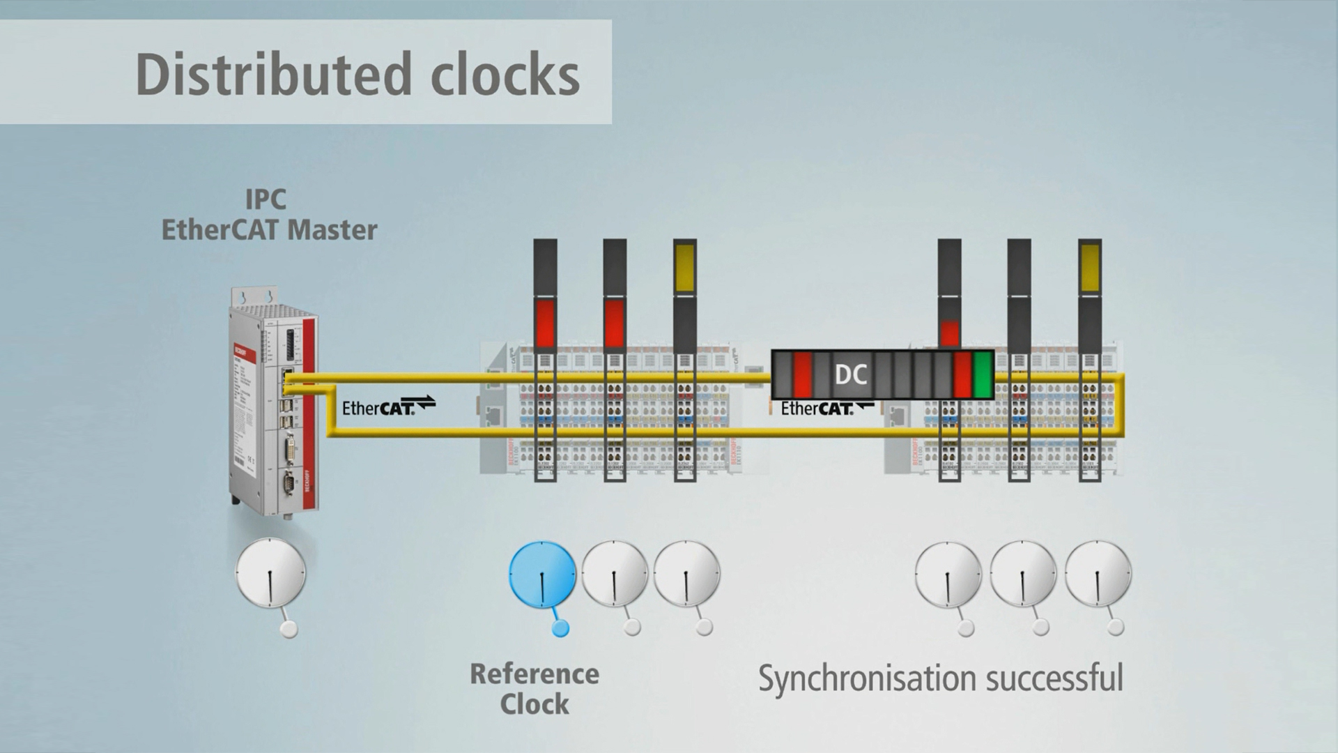
Distributed Clocks: the integrated time management system in EtherCAT
Measurement technology easily configured: Analog EtherCAT input terminals.

Measurement technology simply integrated: With the analog EtherCAT Terminals.

Decentralised, end-to-end system synchronisation: With Distributed Clocks and EtherCAT.

The EL3174 analog input terminal has four individually parameterizable inputs. Signals in the range from -10/0 to +10 V or -20/0/+4 to +20 mA can be processed via each channel. Physically, the voltage and current signals should be connected to different terminal points. Each channel should then be set by the controller/TwinCAT to U or I mode via CoE. The voltage inputs operate differentially; the current inputs are single-ended. All inputs are digitized with a resolution of 16 bits and transmitted, electrically isolated, to the higher-level automation device. With a technical measuring range of ±107% of the nominal range, the terminal also supports commissioning with sensor values in the limit range and diagnostics according to NAMUR NE43.
Product status:
regular delivery
Product information
| Technical data | EL3174 |
|---|---|
| Number of inputs | 4 |
| Ground reference (input) | voltage: differential, current: single-ended |
| Power supply | via the E-bus |
| Oversampling factor | – |
| Distributed clocks | yes |
| Distributed clock accuracy | << 1 µs |
| Internal resistance | > 200 kΩ | typ. 85 Ω |
| Input filter cut-off frequency | 5 kHz |
| Common mode voltage UCM | max. 35 V (voltage measurement) |
| Dielectric strength | max. 30 V (current measurement) |
| Conversion time | minimum 150 µs |
| Measuring range, nominal | -10/0…+10 V | -20/0/+4…+20 mA |
| Measuring range, technical | -10.73…+10.73 V | -21.47…+21.47 mA |
| Resolution | 16 bit (incl. sign) |
| Measurement error/uncertainty | < ±0.3% (relative to full scale value) |
| Electrical isolation | 500 V (E-bus/signal voltage) |
| Current consumption E-bus | typ. 180 mA |
| Current consumption power contacts | load-dependent |
| Bit width in the process image | inputs: 16 byte |
| Configuration | no address or configuration setting |
| Special features | U/I parameterizable, ExtendedRange, standard and compact process image, activatable FIR/IIR filters |
| Weight | approx. 65 g |
| Operating temperature | -25…+60°C |
| Storage temperature | -40…+85°C |
| Relative humidity | 95%, no condensation |
| Vibration/shock resistance | conforms to EN 60068-2-6/EN 60068-2-27 |
| EMC immunity/emission | conforms to EN 61000-6-2/EN 61000-6-4 |
| Protect. rating/installation pos. | IP20/variable |
| Approvals/markings | CE, CCC, UL, ATEX, IECEx, cFMus |
| Ex marking | ATEX: II 3G Ex ec IIC T4 Gc IECEx: Ex ec IIC T4 Gc cFMus: Class I, Division 2, Groups A, B, C, D Class I, Zone 2, AEx ec IIC T4 Gc |
| Housing data | EL-12-16pin |
|---|---|
| Design form | HD (High Density) housing with signal LEDs |
| Material | polycarbonate |
| Installation | on 35 mm DIN rail, conforming to EN 60715 with lock |
| Side by side mounting by means of | double slot and key connection |
| Marking | labeling of the BZxxxx series |
| Wiring | solid conductors (s): direct plug-in technology; fine-stranded conductors (st) and ferrule (f): spring actuation by screwdriver |
| Connection cross-section | s*: 0.08…1.5 mm², st*: 0.25…1.5 mm², f*: 0.14…0.75 mm² |
| Connection cross-section AWG | s*: AWG28…16, st*: AWG22…16, f*: AWG26…19 |
| Stripping length | 8…9 mm |
| Current load power contacts | Imax: 10 A |
| Dimensions (W x H x D) | 12 mm x 100 mm x 68 mm |
*s: solid wire; st: stranded wire; f: with ferrule
Loading content ...
Loading content ...
Loading content ...
Loading content ...
© Beckhoff Automation 2026 - Terms of Use