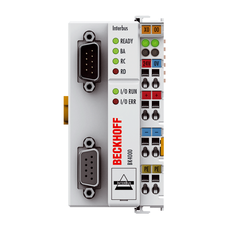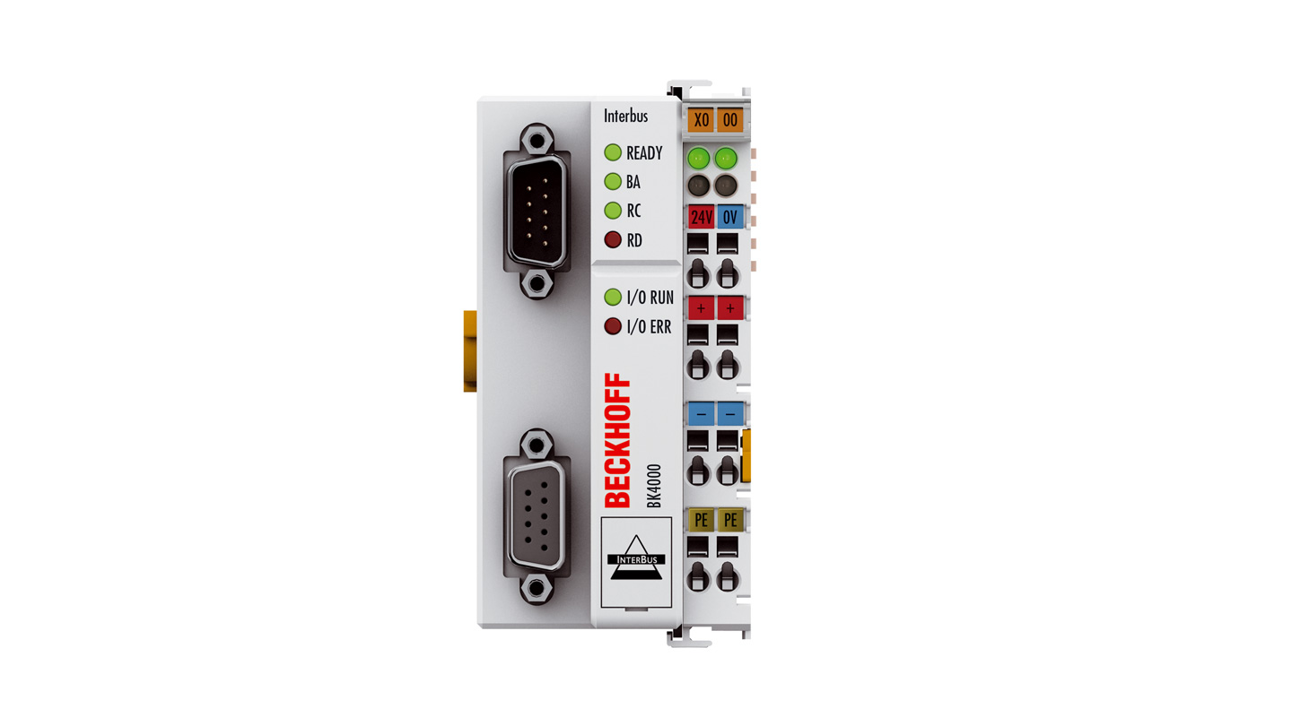
The BK4000 Bus Coupler connects the Interbus bus system to the electronic terminal blocks, which can be extended in modular fashion. One unit consists of one Bus Coupler, any number of up to 64 terminals and one end terminal.
The number of analog channels is limited by the Interbus protocol to a maximum of 32 input and 32 output channels. The transmission rate is 500 kbaud. Slave devices can be spaced up to 400 m from each other as the fieldbus interface acts as repeater. The overall length of an Interbus ring is limited to 13 km.
The identification code and the length code are determined by the Bus Coupler automatically after starting, depending upon the connected Bus Terminal, and are read out by the master. It is not necessary to parameterize the slave.
The Bus Coupler recognizes the connected terminals and automatically generates the affiliations of the inputs/outputs to the bytes of the process image. The first input/output signal is inserted in the first bit of one word (LSB), beginning from the left. The Bus Coupler inserts further signals in this word. Inputs and outputs are clearly separated.
Interbus has been established as an open fieldbus system since 1987. Interbus has a ring structure, and up to 256 stations can be operated in a ring. Data transmission takes place at 500 kbaud. Due to the efficient data transmission, sensor and actuator data can be transferred over great distances.
The Interbus coupler works with the protocol chip SUPI3 and supports the extended diagnostics of the Interbus master. Byte-by-byte addressing in the master is supported as from generation G4.
Product status:
regular delivery (not recommended for new projects) | recommended alternative: BK4020
Product information
| Technical data | BK4000 |
|---|---|
| Number of Bus Terminals | 64 |
| Max. number of bytes fieldbus | 64 byte input and 64 byte output |
| Digital peripheral signals | 512 inputs/outputs |
| Analog peripheral signals | 32 inputs/outputs |
| Configuration possibility | via KS2000 |
| Data transfer rates | 500 kbaud |
| Bus interface | 2 x D-sub plug, 9-pin, plug and socket with screening and vibration lock |
| Data transfer medium | LiYCY 3 x 2 x 0.22 mm² |
| Power supply | 24 V DC (-15%/+20%) |
| Input current | 70 mA + (total K-bus current)/4, 500 mA max. |
| Starting current | 2.5 x continuous current |
| Recommended fuse | ≤ 10 A |
| Current supply K-bus | 1750 mA |
| Power contacts | max. 24 V DC/max. 10 A |
| Electrical isolation | 500 V (power contact/supply voltage/fieldbus) |
| Data transfer time | approx. 1 ms in the case of 10 modules for 32 bit input and output each |
| Weight | approx. 170 g |
| Operating/storage temperature | 0…+55°C/-25…+85°C |
| Relative humidity | 95%, no condensation |
| Vibration/shock resistance | conforms to EN 60068-2-6/EN 60068-2-27 |
| EMC immunity/emission | conforms to EN 61000-6-2/EN 61000-6-4 |
| Protect. rating/installation pos. | IP20/variable |
| Approvals/markings | CE, UL, ATEX, IECEx |
| Ex marking | ATEX: II 3 G Ex ec IIC T4 Gc IECEx: Ex ec IIC T4 Gc |
| Housing data | BKxxxx, BCxxxx |
|---|---|
| Design form | compact terminal housing with signal LEDs |
| Material | polycarbonate |
| Dimensions (W x H x D) | 51 mm x 100 mm x 69 mm |
| Installation | on 35 mm DIN rail, conforming to EN 60715 with lock |
| Side by side mounting by means of | double slot and key connection |
| Marking | labeling of the BZxxx series |
| Wiring | solid conductor (s), flexible conductor (st) and ferrule (f): spring actuation by screwdriver |
| Connection cross-section | s*: 0.08…2.5 mm², st*: 0.08…2.5 mm², f*: 0.14…1.5 mm² |
| Stripping length | 8…9 mm |
| Current load power contacts | Imax: 10 A |
*s: solid wire; st: stranded wire; f: with ferrule
Loading content ...
Loading content ...
Loading content ...
© Beckhoff Automation 2024 - Terms of Use


