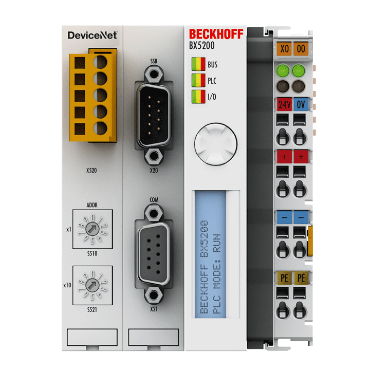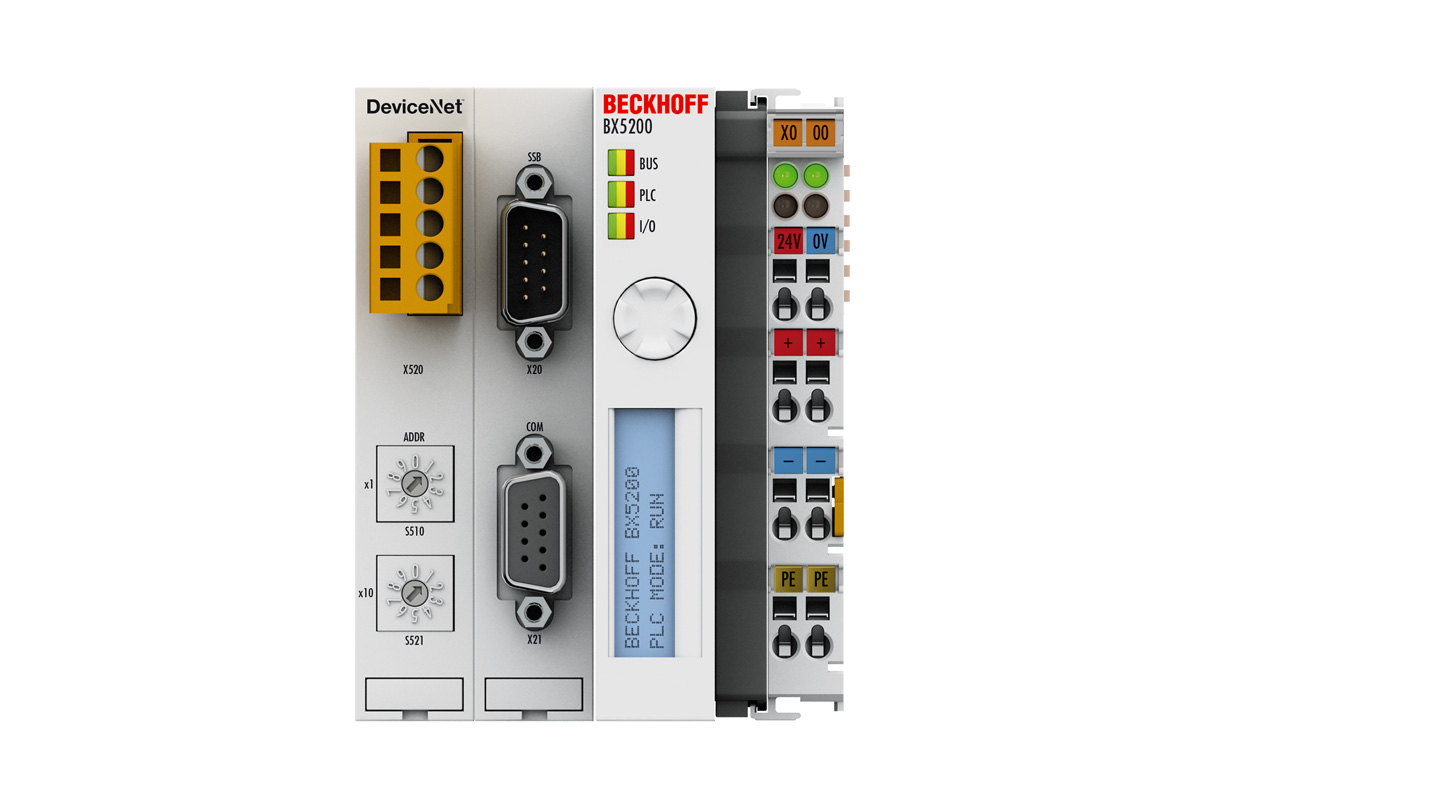
The BX5200 Bus Terminal Controller has a DeviceNet® slave interface. It has automatic baud rate detection up to 500 kbaud and an address selection switch for address assignment. Up to 512 byte of input and 512 byte of output can be exchanged with the controller.
One unit consists of the BX5200 Bus Terminal Controller with up to 64 Bus Terminals and a bus end terminal. With the terminal bus extension system, the connection of up to 255 Bus Terminals is possible. The controller is programmed via the COM1 or via the DeviceNet® interface of the FC510x PC Fieldbus Card.
In terms of their equipment and performance, the BX series Bus Terminal Controllers are positioned between the BC series Bus Terminal Controllers and the CX series Embedded PCs. The main features distinguishing BC and BX are the larger memory and the expanded interfaces of the BX. Additionally, two serial interfaces are integrated for programming and for the connection of further serial devices. The device itself comprises an illuminated LC display with two lines of 16 characters each, a joystick switch and a real-time clock. Further peripheral devices, e.g. displays, can be connected via the integrated Beckhoff Smart System Bus (SSB).
The BX family is particularly suitable for a modular machine concept. Within a network, the Bus Terminal Controller can exchange data with other system parts via the fieldbus interfaces. The real-time clock enables decentralized applications, for which the day of the week or the time play an important role. The areas of application of this series are similar to that of the BC series, but due to the larger memory the BX can execute significantly more complex and larger programs and can manage more data locally (e.g. history and trend data recording), which are then successively fetched over the fieldbus.
Controller for distributed signal processing
Like for all other Beckhoff controllers, the TwinCAT automation software is the basis for parameterization and programming. The BX devices are programmed according to the powerful IEC 61131-3 standard in the programming languages IL, FBD, LD, SFC or ST. Users therefore have the familiar TwinCAT tools available, e.g. the PLC programming interface, the System Manager and TwinCAT Scope. Data is exchanged optionally via the serial port (COM1) or via the fieldbus through Beckhoff FC520x PC Fieldbus Cards.
The configuration is also carried out using TwinCAT. The fieldbus interface, the SSB bus and the real-time clock can be configured and parameterized via the System Manager. The System Manager can read all connected devices and Bus Terminals. After the parameterization, the configuration is saved on the BX via the serial interface and can be accessed again later.
Product status:
regular delivery (not recommended for new projects)
Product information
| PLC data | DeviceNet® | BX5200 |
|---|---|
| Programming | TwinCAT (via programming interface or fieldbus) |
| Program memory | 256 kbytes |
| Data memory | 256 kbytes |
| Remanent data | 2 kbytes |
| Persistent data | 1 kbyte |
| Runtime system | 1 PLC task |
| PLC cycle time | approx. 1 ms for 1,000 instructions (without I/O cycle, K-bus) |
| Programming languages | IEC 61131-3 (IL, LD, FBD, SFC, ST) |
| Online change | yes |
| Up/down load code | yes/yes |
| Technical data | BX5200 |
|---|---|
| Number of Bus Terminals | 64 (255 with K-bus extension) |
| Max. number of bytes fieldbus | 512 byte input and 512 byte output |
| Max. number of bytes process image | 2048 byte input and 2048 byte output |
| Digital peripheral signals | 2,040 inputs/outputs |
| Analog peripheral signals | 512 inputs/outputs |
| Data transfer rates | automatic detection up to 500 kbaud |
| Bus interface | open style connector, 5-pin |
| Interfaces | COM1: 1 x RS232, COM2: 1 x RS232 or RS485 |
| SSB | CANopen-based subsidiary bus system for the connection of further peripheral devices |
| Diagnostics LED | 2 x power supply, 2 x K-bus |
| Display | FSTN display with 2 x 16 characters for diagnosis or own texts, illuminated |
| Switch | joystick switch for parameterisation and diagnosis |
| Clock | battery-powered real-time clock for time and date |
| Power supply | 24 V DC (-15%/+20%) |
| Input current | 140 mA + (total K-bus current)/4, 500 mA max. |
| Starting current | 2.5 x continuous current |
| Current supply K-bus | 1450 mA |
| Power contacts | max. 24 V DC/max. 10 A |
| Electrical isolation | 500 V (power contact/supply voltage) |
| Weight | approx. 250 g |
| Operating temperature | -25…+60°C |
| Storage temperature | -40…+85°C |
| Relative humidity | 95%, no condensation |
| Vibration/shock resistance | conforms to EN 60068-2-6/EN 60068-2-27 |
| EMC immunity/emission | conforms to EN 61000-6-2/EN 61000-6-4 |
| Protect. rating/installation pos. | IP20/variable |
| Approvals/markings | CE, UL |
| Housing data | BXxxxx |
|---|---|
| Design form | compact terminal housing with signal LEDs |
| Material | polycarbonate |
| Installation | on 35 mm DIN rail, conforming to EN 60715 with lock |
| Side by side mounting by means of | double slot and key connection |
| Marking | labeling of the BZxxxx series |
| Wiring | solid conductor (s), flexible conductor (st) and ferrule (f): spring actuation by screwdriver |
| Connection cross-section | s*: 0.08…2.5 mm², st*: 0.08…2.5 mm², f*: 0.14…1.5 mm² |
| Stripping length | 8…9 mm |
| Current load power contacts | Imax: 10 A |
| Dimensions (W x H x D) | 81 mm x 100 mm x 90 mm (BX8000: 61 mm x 100 mm x 90 mm) |
*s: solid wire; st: stranded wire; f: with ferrule
Loading content ...
Loading content ...
Loading content ...
Loading content ...
© Beckhoff Automation 2026 - Terms of Use


