
EPP2596-0002 | EtherCAT P Box, 1-channel LED output, 0…24 V DC, 3 A, M12


2 | Rx+/GNDP
3 | Rx-/UP
4 | Tx-/US
1 | LED+
2 | n.c.
3 | LED-
4 | n.c.
5 | Shield
X02
1,2 | 24 V LED
3,4 | GND LED
5 | Shield
X03
1 | 24 V Cam
2 | TrigIn
3 | GNDS
4 | TrigOut
5 | Shield
X04
1 | 24 V Cam
2 | TrigIn
3 | GNDS
4 | TrigOut
5 | Shield

EPP2596-0002 | EtherCAT P Box, 1-channel LED output, 0…24 V DC, 3 A, M12

The EPP2596-0002 LED strobe control box contains a flexible power supply unit that supplies the LED with the required current and voltage. Applications from continuous light to short light pulses in the kHz range are thus possible. Each individual flash can be triggered in a controlled manner by the control system via the distributed clocks/timestamp function. The EPP2596-0002 has a trigger output for triggering cameras and high-quality, fast current and voltage control, so that line scan cameras, for example, also benefit from constant illumination. Extensive real-time diagnostics, e.g. for input current/voltage and output current/voltage allow detailed monitoring of the LED light intensity. Thus, overdrive applications with short high-current pulses through the LED are possible. If the set load corridor is exited, e.g., due to load errors, the EPP2596-0002 switches off to protect the LED (resettable).
Special features:
- suitable for lighting-related vision applications up to 24 V DC
- max. output current 0…3 A in pulse mode/0…1.2 A in continuous mode
- different operating modes possible
- continuous mode (current and voltage output, PWM)
- pulse operation
- RGB/common anode mode
- support of the timestamp XFC technology
- synchronized operation through distributed clocks XFC technology possible
Product status:
product announcement | estimated market release 3rd quarter 2026
Product information
| Technical data | EPP2596-0002 |
|---|---|
| Protocol | EtherCAT |
| Bus interface | 2 x M8 socket, P-coded, shielded |
| Number of outputs | 1 |
| Output connections | M12 x 1, 5-pin, a-coded |
| Nominal output voltage | 24 V DC (-15%/+20%) |
| Max. output current | 0…3 A in pulsed mode (depending on output voltage and duty cycle)
0…1.2 A in continuous mode |
| Trigger output (to camera) | 24 V DC |
| Trigger input (from camera) | 24 V DC |
| Switching times | typ. TON: < 1 µs, typ. TOFF: < 1 µs, pulses from 25 µs…10 s |
| Distributed clocks | yes |
| Distributed clock precision | << 1 µs |
| Output voltage | continuous light mode : 0…UIN
continuous light operation PWM: 0…(UIN - 0.5 V) pulsed operation (0…2 A): 0…(UIN - 2 V) pulsed operation (3 A*): 0…(UIN - 3 V) *linear behavior of the maximum output voltage between 2 A and 3 A |
| Current consumption from US | typ. 100 mA |
| Electrical isolation | 500 V |
| Special features | constant voltage, constant current and PWM as available operating modes, extensive real-time diagnostics, continuous LED operation, RGB/common anode operation |
| Weight | approx. 165 g |
| Operating temperature | -25…+60°C |
| Storage temperature | -40…+85°C |
| Vibration/shock resistance | conforms to EN 60068-2-6/EN 60068-2-27 |
| EMC immunity/emission | conforms to EN 61000-6-2/EN 61000-6-4 |
| Protect. rating/installation pos. | IP65/66/67 (conforms to EN 60529)/variable |
| Approvals/markings | CE, UL (in preparation) |
| Housing data | 8 x M8, 4 x M12 |
|---|---|
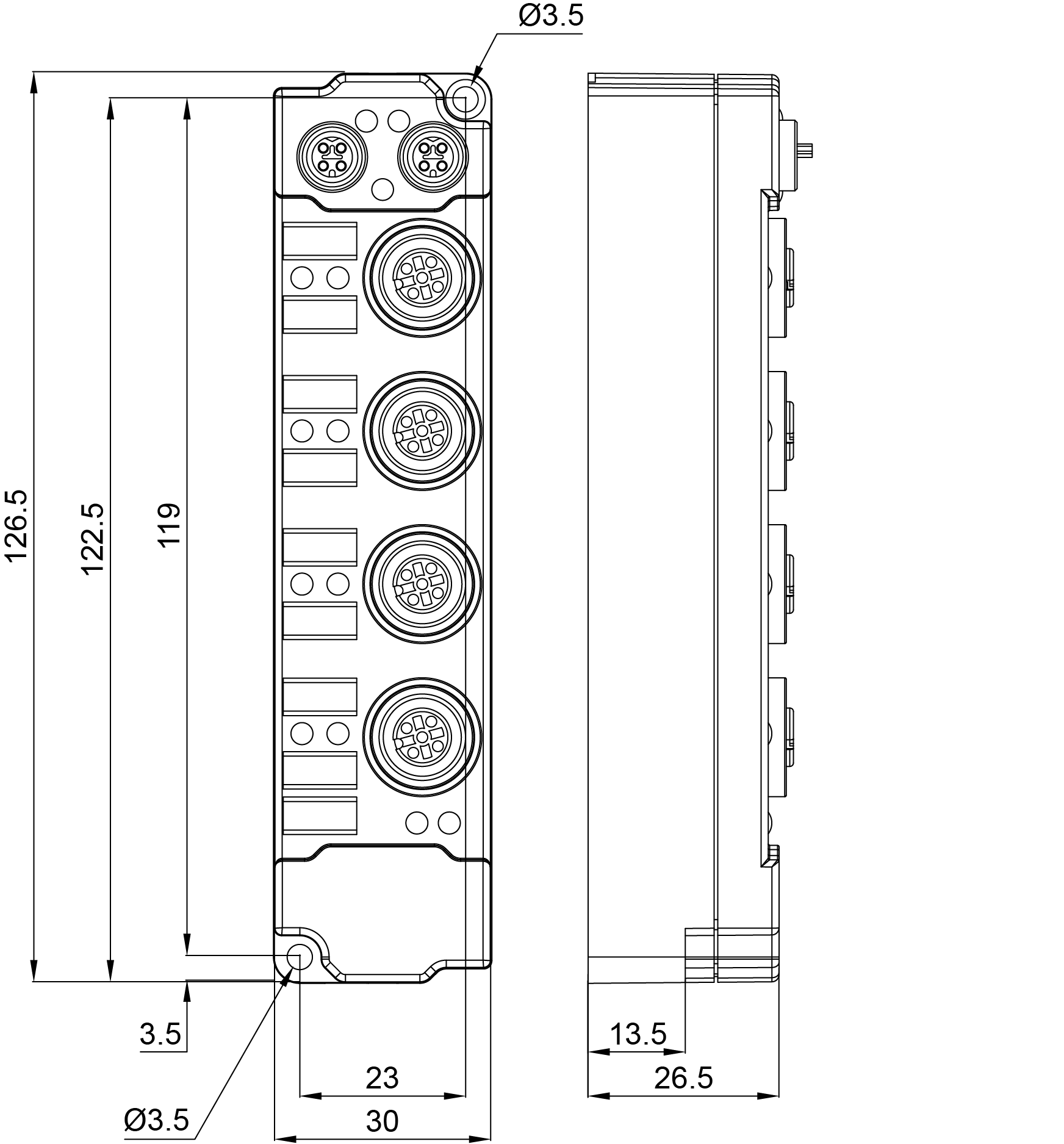
| Dimensions (W x H x D) | 30 mm x 126 mm x 26.5 mm |
| Material | PA6 (polyamide) |
| Installation | 2 fixing holes 3.5 mm diameter for M3 |
Loading content ...
| Material compliance | EPP2596-0002 |
|---|---|
| CAS No. | 7439-92-1, 115-86-6 |
| REACH SVHC | Lead, Triphenyl phosphate |
| REACH Annex XVII | compliant |
| REACH Annex XIV | compliant |
| SCIP No. | SCIP submission in progress |
| POP | compliant |
| RoHS | compliant with exemption |
| RoHS exemption | 6c: Copper alloy with a mass fraction of up to 4% lead, 7c-I: Lead-containing electrical and electronic components in glass and ceramic materials, excluding dielectric ceramics in capacitors |
| China-RoHS | www.beckhoff.com/china-rohs-io |
| CA Prop65 | www.beckhoff.com/prop65 |
| Disclaimer | This statement and the information contained above are, to the best of our knowledge and belief, accurate, based on the information we have received from our suppliers. This information is in line with the current standard of technology and our suppliers’ technical documentation. The absence of the substances is not verified by Beckhoff Automation by means of analytical tests. When addressed to our customers any information contained in this document is subject to the terms and conditions expressed in the governing customer agreement. Our general terms and conditions apply. |
Loading content ...
Loading content ...
Loading content ...
© Beckhoff Automation 2026 - Terms of Use