
ELX3312 | EtherCAT Terminal, 2-channel analog input, temperature, thermocouple, 16 bit, Ex i


+24 V Ex
0 V Ex

ELX3312 | EtherCAT Terminal, 2-channel analog input, temperature, thermocouple, 16 bit, Ex i
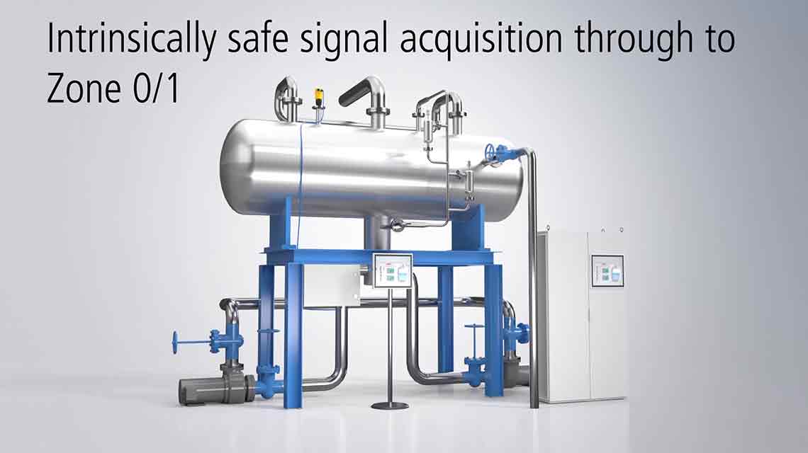
The system-integrated solution for explosion protection: PC-based control

The ELX3312 analog input terminals allow the direct connection of thermocouples located in hazardous areas classified zone 0/20 or 1/21. The circuitry of the ELX3312 can operate sensors with 2-wire technology. Linearization is possible over the entire freely selectable temperature range. The error LEDs indicate a broken wire. Compensation for the cold junction is achieved through internal temperature measurement. Voltage measurement in the mV range is also possible with the ELX3312.
EtherCAT terminals of the ELX series must always be operated in conjunction with the ELX9560 power supply terminal. This terminal generates an electrically isolated output voltage (24 V EX) from the input voltage (24 V DC) for supplying the subsequent ELX terminals. If a new power supply is required, the combination of an ELX9410 and an ELX9560 can be used so that further ELX terminals can be added.
The ELX terminal segment must be terminated with one ELX9012, two ELX9410 or one EK1110. The use of two ELX9410 allows the use of EL terminals behind ELX terminals. With the EK1110, the terminal segment can be continued via an EtherCAT cable, for example to implement cable redundancy.
Product status:
regular delivery
Product information
| Technical data | ELX3312 |
|---|---|
| Technology | Temperature measurement |
| Sensor types | thermocouples type K, J, L, E, T, N, U, B, R, S, C (default: type K) |
| Number of inputs | 2 (differential) |
| Connection technology | 2-wire |
| Measuring range | depending on sensor type, type K -270…+1370°C, voltage measurement: ±30…±75 mV, for further types and details see documentation |
| Resolution | 0.1°C per digit |
| Measurement error/uncertainty | < ±0.3% (relative to full scale value) |
| Internal resistance | typ. ≥ 10 kΩ (differential) |
| Input filter limit frequency | typ. 1 kHz; depending on sensor length, conversion time, sensor type |
| Conversion time | 10…5000 ms (adjustable, default: 270 ms) |
| Supply voltage electronics | 24 V DC (via power contacts), ELX9560 power supply |
| Current consumption power contacts | typ. 10 mA |
| Current consumption E-bus | typ. 70 mA |
| Special features | limit value monitoring, digital filter and characteristic curve linearization integrated |
| Weight | approx. 60 g |
| Operating temperature | -25…+60°C |
| Storage temperature | -40…+85°C |
| Relative humidity | 95%, no condensation |
| Vibration/shock resistance | conforms to EN 60068-2-6/EN 60068-2-27 |
| EMC immunity/emission | conforms to EN 61000-6-2/EN 61000-6-4 |
| Protect. rating/installation pos. | IP20/see documentation |
| Approvals/markings | CE, UL, ATEX, IECEx, cFMus, CCC |
| Ex marking | ATEX: II 3(1)G Ex ec [ia Ga] IIC T4 Gc II (1)D [Ex ia Da] IIIC I (M1) [Ex ia Ma] I IECEx: Ex ec [ia Ga] IIC T4 Gc [Ex ia Da] IIIC [Ex ia Ma] I cFMus: AIS Class I, II, III, Division 1, Groups A thru G Class I, Division 2, Groups A, B, C, D Class I, Zone 2, AEx ec [ia Ga] IIC T4 Gc [AEx ia Da] IIIC T4 |
| Housing data | ELX-12-8pin |
|---|---|
| Design form | compact terminal housing with signal LEDs |
| Material | polycarbonate, blue |
| Dimensions (W x H x D) | 12 mm x 100 mm x 68 mm |
| Installation | on 35 mm DIN rail, conforming to EN 60715 with lock |
| Side by side mounting by means of | double slot and key connection |
| Marking | labeling of the BZxxxx series |
| Wiring | solid conductor (s), flexible conductor (st) and ferrule (f): spring actuation by screwdriver |
| Connection cross-section | s*: 0.08…2.5 mm², st*: 0.08…2.5 mm², f*: 0.14…1.5 mm² |
| Connection cross-section AWG | s*: AWG28…14, st*: AWG28…14, f*: AWG26…16 |
| Stripping length | 8…9 mm |
| Power contacts | 2 blade/spring contacts |
*s: solid wire; st: stranded wire; f: with ferrule
Loading content ...
| Material compliance | ELX3312 |
|---|---|
| CAS No. | 7439-92-1 |
| REACH SVHC | Lead |
| REACH Annex XVII | compliant |
| REACH Annex XIV | compliant |
| SCIP No. | SCIP submission in progress |
| POP | compliant |
| RoHS | compliant with exemption |
| RoHS exemption | 7a: Lead in solders with a high melting point with a minimum mass fraction of 85% lead, 7c-I: Lead-containing electrical and electronic components in glass and ceramic materials, excluding dielectric ceramics in capacitors |
| China-RoHS | www.beckhoff.com/china-rohs-io |
| CA Prop65 | www.beckhoff.com/prop65 |
| Disclaimer | This statement and the information contained above are, to the best of our knowledge and belief, accurate, based on the information we have received from our suppliers. This information is in line with the current standard of technology and our suppliers’ technical documentation. The absence of the substances is not verified by Beckhoff Automation by means of analytical tests. When addressed to our customers any information contained in this document is subject to the terms and conditions expressed in the governing customer agreement. Our general terms and conditions apply. |
Loading content ...
Loading content ...
© Beckhoff Automation 2026 - Terms of Use