
ER2349-0021 | EtherCAT Box, 16-channel digital combi, 24 V DC, 10 µs, 0.5 A, M8, zinc die-cast


connection
2 | Rx+
3 | Rx-
4 | Tx-
3 | GNDP
4 | In-/Output
2 | +24 V DC UP
3 | GNDS
4 | GNDP

ER2349-0021 | EtherCAT Box, 16-channel digital combi, 24 V DC, 10 µs, 0.5 A, M8, zinc die-cast

The ER2349-0021 EtherCAT Box has 16 digital channels, each of which can optionally be operated as an input or as an output. A configuration for using a channel as input or output is not necessary; the input circuit is internally connected to the output driver, so that a set output is displayed automatically in the input process image.
A filter constant of 10 µs is available for the inputs. The outputs are short-circuit proof and protected against inverse polarity. They handle load currents of up to 0.5 A each, although the total current is limited to 4 A. The state of each signal is indicated by means of light emitting diodes. The signals are connected via M8 screw type connectors. The sensors are powered by the load voltage UP.
The EtherCAT Box modules with zinc die-cast housing are ready for use in harsh industrial and process environments. With the fully sealed design and metal surfaces the ER series is ideal for applications requiring enhanced load capacity and protection against weld spatter, for example.
Product status:
regular delivery
Product information
| Technical data | ER2349-0021 |
|---|---|
| Protocol | EtherCAT |
| Bus interface | 2 x M8 socket, 4-pin, a-coded, shielded |
| Specification | EN 61131-2, type 1/3 |
| Number of channels | 16 digital inputs or outputs |
| Input/output connections | M8 x 1, 3-pin, a-coded |
| Input filter | 10 µs |
| “0” signal voltage | -3…+5 V |
| “1” signal voltage | 11…30 V, 6 mA input current (EN 61131-2, type 3) |
| Sensor supply | from load supply voltage, max. 0.5 A, short-circuit proof in total |
| Load type | ohmic, inductive, lamp load |
| Rated load voltage | 24 V DC (-15%/+20%) |
| Max. output current | 0.5 A per channel, individually short-circuit proof, ∑ 4 A |
| Switching times | typ. TON: 60 µs, typ. TOFF: 300 µs |
| Short-circuit current | typ. 1.5 A |
| Distributed clocks | – |
| Auxiliary power current | typ. 20 mA + load |
| Current consumption from US | typ. 130 mA |
| Power supply connection | feed: 1 x M8 male socket, 4-pin, a-coded; downstream connection: 1 x M8 female socket, 4-pin, a-coded |
| Electrical isolation | 500 V |
| Special features | freely configurable inputs or outputs |
| Weight | approx. 450 g |
| Operating temperature | -25…+60°C |
| Storage temperature | -40…+85°C |
| Vibration/shock resistance | conforms to EN 60068-2-6/EN 60068-2-27 |
| EMC immunity/emission | conforms to EN 61000-6-2/EN 61000-6-4 |
| Protect. rating/installation pos. | IP65/66/67 (conforms to EN 60529)/variable |
| Approvals/markings | CE, UL |
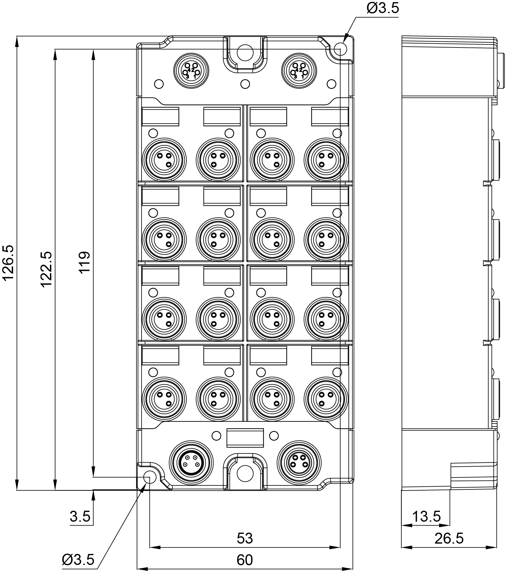
| Housing data | 16 x M8, 8 x M12 |
|---|---|
| Dimensions (W x H x D) | 60 mm x 126 mm x 26.5 mm |
| Material | zinc die-cast |
| Installation | 2 fixing holes 3.5 mm diameter for M3; 2 fixing holes 4.5 mm diameter for M4 |
Loading content ...
Loading content ...
Loading content ...
© Beckhoff Automation 2026 - Terms of Use