
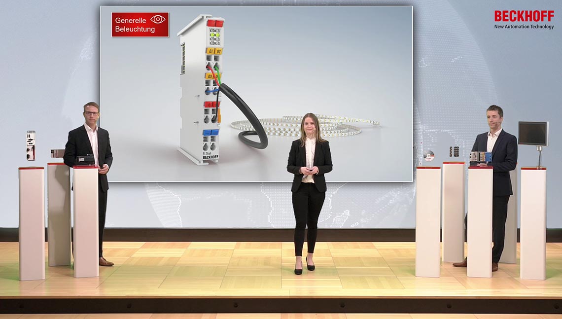
EL2596 | EtherCAT Terminal, 1-channel LED output, 0…24 V DC, 3 A
Output
Trigger Out
Trigger In
Power out
Warning
Device error
+24 V

+24 V DC
0 V


Connection of an LED

EL2596 | EtherCAT Terminal, 1-channel LED output, 0…24 V DC, 3 A

Connection of an LED

Exact current control and synchronization of LED lamps
I/O innovations and optimization of your machines by using PC-based control
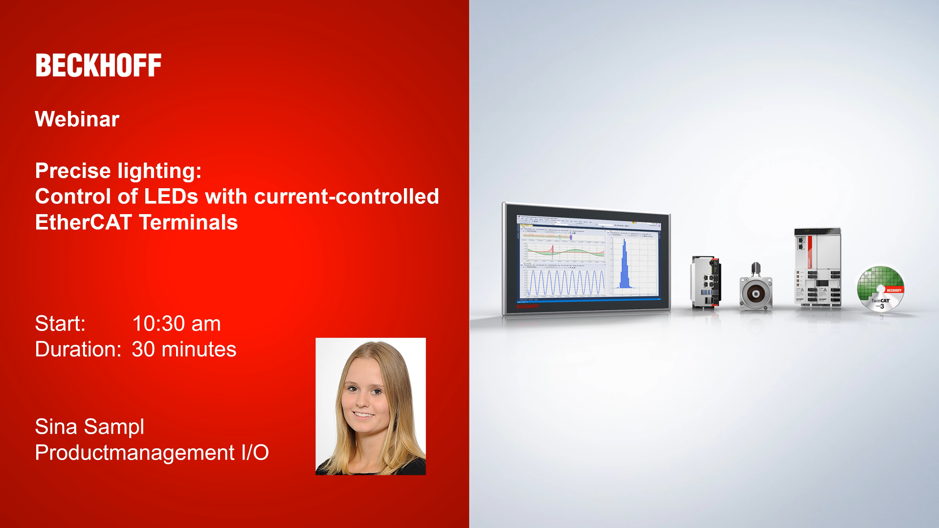
Precise lighting: Control of LEDs with current-controlled EtherCAT Terminals
EtherCAT timestamp: high-precision interaction of controller and environment – to the exact nanosecond
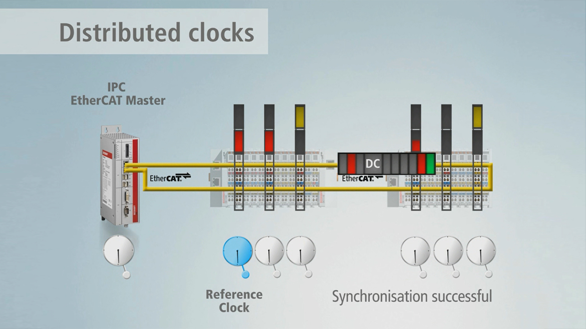
Distributed Clocks: the integrated time management system in EtherCAT

SPS IPC Drives 2018:

Decentralised, end-to-end system synchronisation: With Distributed Clocks and EtherCAT.

The EL2596 LED strobe control terminal contains a flexible power supply unit that supplies the LED with the required current and voltage. Applications from continuous light to short light pulses in the kHz range are thus possible. Each individual flash can be triggered in a controlled manner by the control system via the distributed clocks/timestamp function. The EL2596 has a trigger output for triggering cameras and high-quality, fast current and voltage control, so that line scan cameras, for example, also benefit from constant illumination. Extensive real-time diagnostics, e.g. for input current/voltage and output current/voltage allow detailed monitoring of the LED light intensity. Thus, overdrive applications with short high-current pulses through the LED are possible. If a specifiable load corridor is exited, e.g., due to load errors, the EL2596 switches off to protect the LED (resettable).
Special features:
- suitable for lighting-related vision applications up to 24 V DC
- max. output current 0…3 A in pulse mode / 0…1.2 A in continuous mode
- different operating modes possible
- continuous mode (current and voltage output, PWM)
- pulse operation
- RGB/common anode mode
- support of XFC technology timestamp
- synchronized operation through distributed clocks XFC technology possible
Recommended use:
- The EL2564 is the right choice for lighting tasks with RGBW LEDs in voltage mode.
- The EL2595 LED terminal of the 1st generation can be used for current-regulated control of LEDs.
- The EL2596 and EL2596-0010 are the significantly more powerful successors of the EL2595 and are therefore suitable for applications requiring high-precision current- and voltage-controlled control of LEDs.
Product status:
regular delivery
Product information
| Technical data | EL2596 |
|---|---|
| Connection technology | 2-wire |
| Number of outputs | 1 |
| Input voltage | 24 V DC (-15%/+20%) |
| Load type | LED (ohmic) |
| Distributed clocks | yes |
| Distributed clock precision | << 1 µs |
| Output voltage | continuous light mode : 0…UIN
continuous light operation PWM: 0…(UIN - 0.5 V) pulsed operation (0…2 A): 0…(UIN - 2 V) pulsed operation (3 A*): 0…(UIN - 3 V) *linear behavior of the maximum output voltage between 2 A and 3 A |
| Max. output current | 0…3 A in pulsed mode (depending on output voltage and duty cycle)
0…1.2 A in continuous mode |
| Switching times | typ. TON: < 1 µs, typ. TOFF: < 1 µs, pulses from 25 µs…10 s |
| Trigger output (to camera) | 1 (electrically isolated, max. 10 mA push-pull, 10…24 V DC, voltage adjustable via externally connectable voltage distributor) |
| Trigger input (from camera) | 1 (electrically isolated, typ. 3 mA, 4…24 V DC, switchable sensitivity) |
| Current consumption E-bus | typ. 240 mA |
| Current consumption power contacts | – |
| Electrical isolation | 500 V (E-bus/field potential) |
| Special features | constant voltage, constant current and PWM as available operating modes; extensive real-time diagnostics; connection option voltage divider TriggerOut; continuous LED operation; RGB/common anode operation |
| Weight | approx. 55 g |
| Operating temperature | 0…55°C |
| Storage temperature | -25…+85°C |
| Relative humidity | 95%, no condensation |
| Vibration/shock resistance | conforms to EN 60068-2-6/EN 60068-2-27 |
| EMC immunity/emission | conforms to EN 61000-6-2/EN 61000-6-4 |
| Protect. rating/installation pos. | IP20/see documentation |
| Approvals/markings | CE |
| Housing data | EL-12-16pin |
|---|---|
| Design form | HD (High Density) housing with signal LEDs |
| Material | polycarbonate |
| Installation | on 35 mm DIN rail, conforming to EN 60715 with lock |
| Side by side mounting by means of | double slot and key connection |
| Marking | labeling of the BZxxxx series |
| Wiring | solid conductors (s): direct plug-in technique; fine-stranded conductors (st) and ferrule (f): spring actuation by screwdriver |
| Connection cross-section | s*: 0.08…1.5 mm², st*: 0.25…1.5 mm², f*: 0.14…0.75 mm² |
| Connection cross-section AWG | s*: AWG28…16, st*: AWG22…16, f*: AWG26…19 |
| Stripping length | 8…9 mm |
| Current load power contacts | Imax: 10 A |
| Dimensions (W x H x D) | 12 mm x 100 mm x 68 mm |
*s: solid wire; st: stranded wire; f: with ferrule
Loading content ...
Loading content ...
Loading content ...
Loading content ...
Loading content ...
Loading content ...
© Beckhoff Automation 2026 - Terms of Use