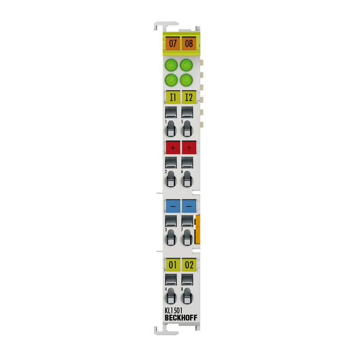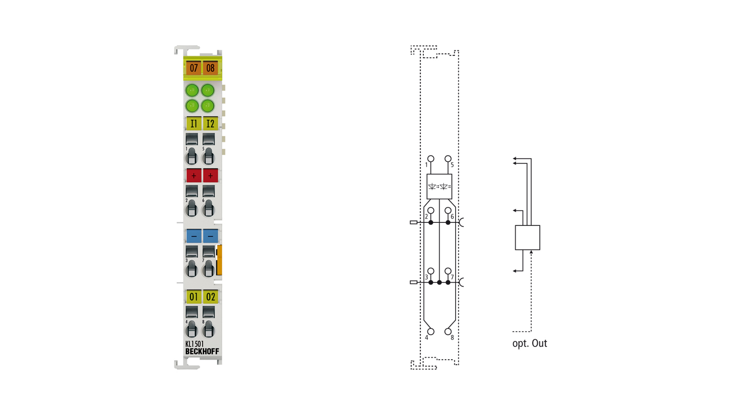
The digital input terminal KL1501 is an up/down counter and transports the counter value electrically isolated to the higher-level automation device. When used as a single-channel up/down counter (32 bits), the pulse is set via the clock input; the counting direction is specified via the U/D input. Furthermore, the input can also be used as a gate input for triggering the counter. In 2-counter mode, two separate counters (Clock and Clock1 inputs), parameterizable as up or down counters, are available with 16 bits each. Both outputs are switched according to the counter state, so that they can be used as fast control signals for field devices. The signal state of the inputs and outputs is indicated by light emitting diodes.
Special features:
- suitable for fast counting tasks with counting frequencies up to 100 kHz
- an up counter and a down counter, or
- two separate up or down counters
Product status:
regular delivery
Product information
| Technical data | KL1501 |
|---|---|
| Connection technology | 1 x up/down counter, 2 x up or down counter |
| Specification | EN 61131-2, type 1, “0”: < 5 V DC, “1”: > 15 V DC, typ. 5 mA |
| Number of counters | 1 or 2 |
| Nominal voltage | 24 V DC (-15%/+20%) |
| “0” signal voltage | -3…+5 V (EN 61131-2, type 1) |
| “1” signal voltage | 15…30 V (EN 61131-2, type 1) |
| Counting frequency | max. 100 kHz (2 kHz for switching up/down) |
| Counter depth | 32 bit |
| Input current | typ. 5 mA (EN 61131-2, type 1) |
| Max. output current | 24 V/0.5 A (short-circuit proof) per channel |
| Current consumption K-bus | typ. 50 mA |
| Current consumption power contacts | load only |
| Electrical isolation | 500 V (K-bus/field potential) |
| Bit width in the process image | 40 inputs/outputs: 32 bit data, 8 bit control/status |
| Configuration | no address setting, configuration via Bus Coupler or controller |
| Special features | set counters, switch outputs |
| Weight | approx. 50 g |
| Storage temperature | -40…+85°C |
| Operating temperature | -25…+60°C |
| Relative humidity | 95%, no condensation |
| Vibration/shock resistance | conforms to EN 60068-2-6/EN 60068-2-27 |
| EMC immunity/emission | conforms to EN 61000-6-2/EN 61000-6-4 |
| Protect. rating/installation pos. | IP20/variable |
| Plug-in wiring level | for all KSxxxx Bus Terminals |
| Approvals/markings | CE, CCC, UL, ATEX, IECEx, cFMus |
| Ex marking | ATEX: II 3 G Ex ec IIC T4 Gc IECEx: Ex ec IIC T4 Gc cFMus: Class I, Division 2, Groups A, B, C, D Class I, Zone 2, AEx ec IIC T4 Gc |
| Housing data | KL-12-8pin | KS-12-8pin |
|---|---|---|
| Design form | compact terminal housing with signal LEDs | terminal housing with pluggable wiring level |
| Material | polycarbonate | |
| Installation | on 35 mm DIN rail, conforming to EN 60715 with lock | |
| Side by side mounting by means of | double slot and key connection | |
| Marking | labeling of the BZxxxx series | |
| Wiring | solid conductor (s), flexible conductor (st) and ferrule (f): spring actuation by screwdriver | |
| Connection cross-section | s*: 0.08…2.5 mm², st*: 0.08…2.5 mm², f*: 0.14…1.5 mm² | s*: 0.08…1.5 mm², st*: 0.08…1.5 mm², f*: 0.14…1.5 mm² |
| Connection cross-section AWG | s*: AWG28…14, st*: AWG28…14, f*: AWG26…16 | s*: AWG28…16, st*: AWG28…16, f*: AWG26…16 |
| Stripping length | 8…9 mm | 9…10 mm |
| Current load power contacts | Imax: 10 A | |
| Dimensions (W x H x D) | 12 mm x 100 mm x 68 mm | |
*s: solid wire; st: stranded wire; f: with ferrule
| Ordering information | |
|---|---|
| KL1501 | Bus Terminal, 1-channel digital input, counter, 24 V DC, 100 kHz |
| KS1501 | Bus Terminal, 1-channel digital input, counter, 24 V DC, 100 kHz, pluggable wiring level |
| KL1501-0010 | Bus Terminal, 1-channel digital input, counter, 24 V DC, 100 kHz, gate reset |
| KL1501-0011 | Bus Terminal, 1-channel digital input, counter, 5 V DC, 100 kHz, with 2 x digital output 24 V DC |
Loading content ...
Loading content ...
Loading content ...
Loading content ...
© Beckhoff Automation 2026 - Terms of Use


