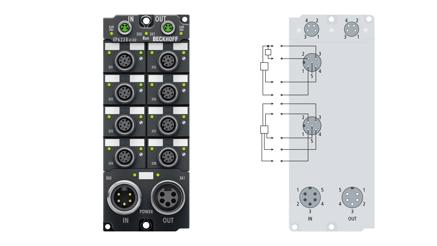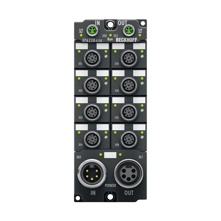
The EP6228-3132 IO-Link module enables connection of up to eight IO-Link devices, e.g. IO-Link box modules, actuators, sensors or combinations thereof. The EP6228-3132 has 4 x Class A and 4 x Class B ports. The Class B ports provide an additional supply voltage for IO-Link devices with higher power requirements. The EP6228-3132 additionally offers further digital inputs on the four Class A master ports. A point-to-point connection is used between the module and the device. The terminal is parameterized via the EtherCAT master. IO-Link is designed as an intelligent link between the fieldbus level and the sensor, wherein parameterization information can be exchanged bidirectionally via the IO-Link connection. The parameterization of the IO-Link devices can be done from TwinCAT via ADS or very conveniently via the integrated IO-Link configuration tool.
In the standard setting, the eight IO-Link channels of the EP6228-3132 operate as an 8-channel input module, 24 V DC, which communicates with connected IO-Link devices as required, parameterizes them and, if necessary, changes their operating mode. Each IO-Link port can optionally be used as a pure input or output.
The 7/8" power supply connectors offer an increased sum current of the EtherCAT Box so that all IO-Link ports can be operated with maximum current.
Product status:
regular delivery
Product information
| Technical data | EP6228-3132 |
|---|---|
| Protocol | EtherCAT |
| Bus interface | 2 x M8 socket, 4-pin, a-coded, shielded |
| Data transfer rates | 4.8 kbaud, 38.4 kbaud and 230.4 kbaud |
| Connection technology | M12 socket, 5-pin, a-coded |
| Number of inputs | 4 digital inputs |
| Nominal input voltage | 24 V DC (-15%/+20%) |
| Input filter | 10 µs |
| “0” signal voltage | -3…+5 V |
| “1” signal voltage | 11…30 V (EN 61131-2, type 3) |
| Input current | typ. 3 mA (EN 61131-2, type 3) |
| Specification version | IO-Link V1.1, 4 x Class A, 4 x Class B |
| IO-Link interfaces | 8 |
| Nominal voltage | 24 V DC (-15%/+20%) |
| Distributed clocks | – |
| IO-Link sensor supply L+ | 24 V DC, 1.4 A per port, ∑ 5.6 A |
| IO-Link extra power P24 | 24 V DC, max. 4.0 A per port, ∑ 4.0 A for 2 ports each for Class B |
| Current consumption from US | typ. 130 mA + load |
| Power supply connection | feed: 1 x 7/8" plug, 5-pin; downstream connection: 1 x 7/8" socket, 5-pin |
| Electrical isolation | 500 V |
| Special features | Class A ports: 1, 2, 5, 6; Class B ports: 3, 4, 7, 8 |
| Weight | approx. 440 g |
| Operating temperature | -25…+60°C |
| Storage temperature | -40…+85°C |
| Vibration/shock resistance | conforms to EN 60068-2-6/EN 60068-2-27 |
| EMC immunity/emission | conforms to EN 61000-6-2/EN 61000-6-4 |
| Protect. rating/installation pos. | IP65/66/67 (conforms to EN 60529)/variable |
| Approvals/markings | CE, UL (in preparation) |
| Housing data | 7/8" infeed |
|---|---|
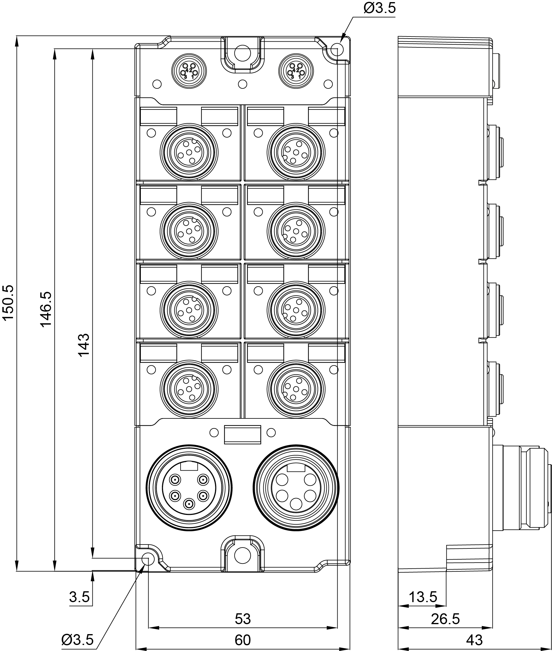
| Dimensions (W x H x D) | 60 mm x 150 mm x 26.5 mm |
| Material | PA6 (polyamide) |
| Installation | 2 fixing holes 3.5 mm diameter for M3; 2 fixing holes 4.5 mm diameter for M4 |
Loading content ...
Loading content ...
Loading content ...
Loading content ...
© Beckhoff Automation 2026 - Terms of Use
