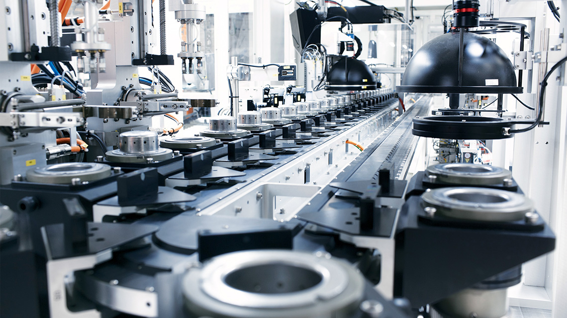
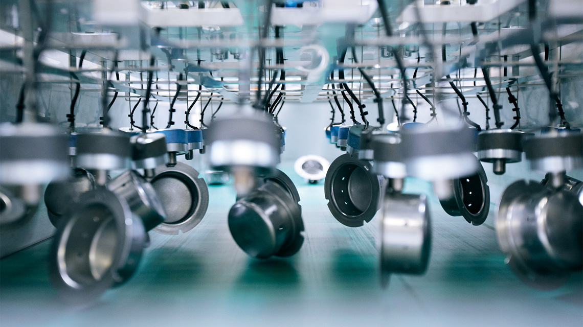
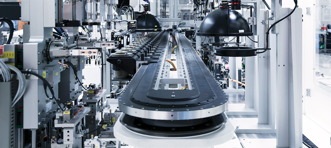
eXtended Transport System (XTS) during the optical quality inspection of cylindrical metal parts
Gefasoft has developed an exceptionally compact installation for the optical inspection of diffusors for airbags via eleven camera stations requiring varying inspection times. With the help of the highly flexible eXtended Transport System, Gefasoft was able to run individual inspection processes in parallel and optimize the product output.
For complex component shapes, optical inspection systems typically require a series of cameras in serial or parallel stations in order to be able to check all pertinent criteria. The Sova-VIS 16 system from Gefasoft Automatisierung und Software GmbH in Regensburg, which inspects diffusors for car airbags, is no exception. Since they are safety-critical components of the car airbags, the cupshaped, drawn sheet metal parts, which are produced in various versions with diameters of approx. 60 millimeters, must be subjected to detailed inspection of their interior and exterior surfaces.
XTS compensates for time differences and simplifies system expansion
While some inspection tasks require only a single picture, others require sophisticated lighting systems and multiple images. The interior wall of the diffusor is a particularly critical surface that must be inspected for even the smallest imperfections with dimensions of only a few tens of micrometers. To achieve the necessary image resolution, line scan cameras are used before the part is trimmed. The trimming process alone takes approximately 2 seconds, which means that the image acquisition times vary greatly between the individual stations.

If all camera stations were linked via a rigid conveyor system like a rotary indexing table, the station with the longest image acquisition time would determine the shortest cycle time of the entire system and limit the throughput rate accordingly. With the flexibility of the XTS solution, on the other hand, faster inspection stations can be served at a higher rate, while slower stations – of which more have been installed – can be supplied with components simultaneously.Gefasoft marketing manager Georg Schlaffer explains: “With the Sova-VIS16 system, the very heterogeneous imaging times of the individual steps caused us to look for a machine layout with a flexible, asynchronous transport system that would enable us to perform the job efficiently in a limited amount of space. The XTS from Beckhoff with its independently controllable movers meets these requirements perfectly. Despite the presence of slower inspection stations, we were able to achieve an average cycle time of 1.9 seconds. The XTS also enabled us to implement this in a footprint that is much smaller than comparable solutions in order to meet the end customer’s space requirements.”
Engineering director Christian Schärtl adds: “Because of the high demand for these parts, the end customer specified a cycle of less than 2 seconds. Since two of the inspection steps take almost 4 seconds, these stations had to be duplicated and parallelized in order to meet this goal, and the flexibility of the XTS made that easy. Other solutions with carriers and switches based on belts or chains would have required much more complex mechanics and would have been slower while taking up more space.”
Because of the many camera inspection stations, the total length of the XTS line amounts to approx. 11 meters (36 feet) with 30 movers. Because of the relatively heavy movers, the line was equipped with a special guidance system made by Hepco. The mass of approx. 4 kilograms (8.8 lbs) per mover was needed to accommodate the handling requirements with units for lifting and rotating, because the diffusors must rotate precisely in front of the cameras and be able to be moved in two layers (“hat” and “cup”) so that their top and bottom can be inspected.
From the beginning, the goal was to use a single inspection machine to fully automate the previously manual process, which ranges from picking up the parts from a pallet to stacking or sorting them via a robot. Distributing the inspection tasks over multiple independent machines was not an economical option for the end customer. Besides the complex logistics between the machines and their increased space requirements, it would also have been too expensive to split up the feeding process of the diffusors from bulk containers. Georg Schlaffer points out another significant advantage of the XTS: “With theXTS we can integrate additional processing stations along the line with great flexibility. This ensures that the system can be adapted to future requirements.
One inspection system for the entire process
After the surface of the components has been degreased, they are supplied to the inspection machine as bulkware in mesh pallets. A gripper takes the parts from a conveyor and passes them to the XTS. To ensure proper orientation for the workpiece holder of the XTS mover, the transfer station has a camera that detects the diffusor’s positional angle as well as its type. Each diffusor has a batch number embossed in its top, which is checked in the first camera station.

After detecting the batch ID, the system checks the interior of the diffusor, which requires it to be rotated in the mover from a “hat” to a “cup” position, i.e. with the opening pointing upward. To do this, the parts are picked up from the mover with a gripper, rotated 180 degrees and placed back onto the mover. In the meantime, the internal mandrel was withdrawn so that the part is centered and resting on its flange. To inspect the surface of the part’s interior, it is then rotated in front of a line scan camera. Christian Schärtl explains: “What turned out to be a major challenge was the limited space, because the camera and four lights had to fit inside the part, which only has an interior diameter of approx. 60 mm. To resolve this, we had to design an integrated lighting and camera unit, which dips into the part while a servomotor docks from the outside to the rotatable mandrel in the mover. In addition, a fast controller had to be developed for the lighting system. Moving the lighting unit into the component and rotating it takes a little over 2 seconds. To achieve the line cycle time of 1.9 seconds, we installed two of these inspection stations.”
The rotating stations are followed by a control station for material deviations and a station for inspecting the base of the diffusor. The last camera station of the first linear XTS section checks the flange for flaws. This means that the first linear section holds six camera stations. With duplicate line scan and rotatingstations, this brings the total to nine positions.
After the movers have passed through the 180-degree curve of the XTS, more camera stations as well as a printing station for marking the diffusors follow on the other side. The parts are flipped from “cup” to “hat” orientation before two parallel line scan camera stations check their exterior surface. This is followed by the inspection of the upper side of the flange, a camera-controlled inkjetprinter for marking faulty components that is synchronized with the motion ofthe XTS movers, and a laser for marking the good parts. At the end of the second linear XTS section, a fast Stäubli TP80 robot picks up the parts from the mover for further processing.
