Automation of a 10 MVA test rig for wind turbines
Major points of interest to the German energy industry right now include the service life of power electronics in wind turbines along with determining the environmental and load conditions that play a role in this regard. Keen to find answers, scientists at the Institute for Electrical Drives, Power Electronics, and Devices (IALB) at the University of Bremen are working closely with the Fraunhofer Institute for Wind Energy Systems (IWES) to learn more. The data set for this project is determined on an enormous test rig, automated with PC-based control from Beckhoff.
Faults in the power electronics are one of the main causes of wind turbine failures. The combination of environmental stresses and electrical operating loads have a significant impact on the service life of the power electronics – and consequently on the wind turbine as a whole. Predicting the effect of these multi-modal loads is therefore hugely important when it comes to avoiding field failures and ensuring long-term product success.
In a bid to determine the causes of the faults, a full-scale test rig with a maximum power of 10.8 MVA generated by four 2.7 MV frequency converters was set up at the University of Bremen. This was within the remit of the “Multidimensional loading of high-performance electronics in wind turbines (HiPE-Wind)” joint project funded by the German Federal Ministry for Economic Affairs and Climate Action (BMWK). The project allows complete wind turbine power control cabinets to be tested under realistic climatic conditions (onshore and offshore) and under different electrical loads to find answers to the following important questions:
- How does the converter system behave when starting up after it has been idle for a long time and has accumulated moisture in the process?
- Does condensation occur?
- How quickly can a turbine be dried out by heating from its own losses?
- Which components or areas in the converter control cabinet are particularly critical?
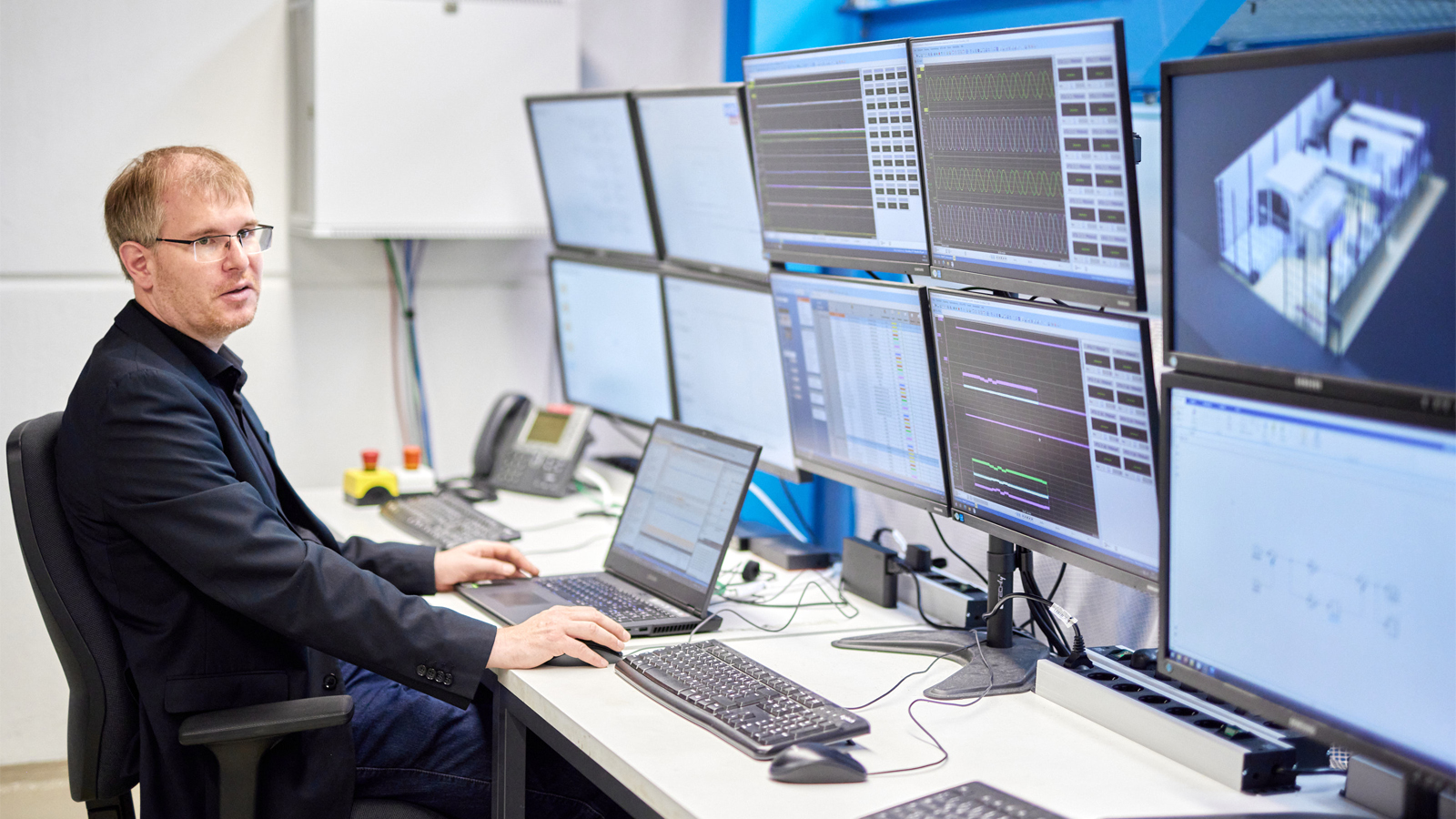
“We wanted to get a better understanding of the factors that influence the service life of power electronics,” explains Professor Bernd Orlik from the IALB at the University of Bremen. The aim was – and is – to develop concepts for optimizing the robustness of power electronics, especially for offshore turbines, and then to test these concepts experimentally. “So far, however, very little is known about how the specific environmental conditions and operating situations that the power electronics are exposed to affect their service life.” Professor Nando Kaminski (also of IALB) adds: “Our preliminary findings show that moisture is particularly critical for power semiconductor components. Electrochemical processes such as corrosion can quickly lead to component failure.”
“As the central wind turbine component, the power electronics control the electrical energy flow of the turbine and are subject to a great deal of stress – for example, from the constantly changing wind conditions and the loads from the grid,” explains Professor Jan Wenske from Fraunhofer IWES. A wide variety of environmental influences are added to this. Ultimately, the decisive factor for the reliability and service life of power electronics is always the combination of loads in the respective system. “Sometimes we make the converters work in very cold conditions, other times in warm environments with high levels of humidity,” says Bernd Orlik. Simultaneously, “normal” electrical loads along with malfunctions and system interactions are simulated as often as required. Similarly, scientists can replicate real environmental conditions from the field in the climate chamber and specifically study the behavior of components under these circumstances. This makes it possible to test the effect of changes in the structure and configuration of a converter in advance, with the advantage being that weaknesses and potential problems can be identified and eliminated as early as the development phase.
Offshore conditions reproduced with climatic cabinet
Anyone who has ever stood in front of a 10 MW wind turbine will have a clear idea of the dimensions of the electronics used. The climate chamber is also large, with a volume of over 170 m³ – or 7.5 x 5.3 x 4.3 m to be precise. This is where the scientists install the control cabinets with the power electronics and connect them to the load converters and the external control unit with PC-based control. Only then do the actual tests begin in all known and conceivable climatic zones. Dry temperatures from -40 to +120°C are just as possible as wet and cold or tropical conditions with a relative humidity of between 10 and 95% in a temperature range from +10 to +95°C. Dynamic, reproducible electrical load profiles enable accelerated aging of the power electronics under the corresponding climatic conditions.
A considerable amount of work goes into making all of this possible in the first place: The test rig consists of the load system with the four frequency converters, a climate room for the test specimen with the corresponding refrigeration/air conditioning and safety technology, and an electrical distribution system which is appropriate for the power. Finally, the researchers run dynamic load simulations with up to 9,000 A (4 x 2,250 A) and voltages between 0 and 1,000 V. “All components have to be controlled simultaneously to achieve reproducible results,” explains Dr. Wilfried Holzke, scientific director of the HiPE-LAB at the University of Bremen, pointing out an initial automation challenge. This is because the various components have to be controlled via different bus systems (Ethernet, PROFINET, Modbus RTU, Modbus TCP, and CANopen) and different protocols. In terms of the safety system, this also has to be easy to integrate into the overall system. All this requires a flexible and powerful automation system. “PC-based control from Beckhoff offers a number of advantages for this,” notes Dr. Wilfried Holzke, “starting with support for a wide range of bus systems and protocols and extending to the integration of HMI and databases. This makes it possible to select the previously created sequences for electrical and climatic loading with ease and transfer them via the PLC to the loading equipment, the climatic room, and the test specimen.
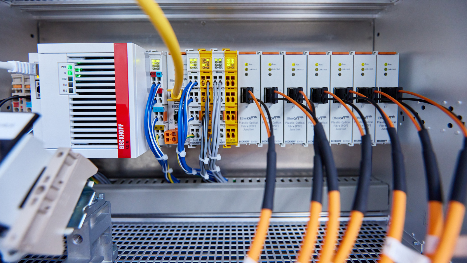
More than 72 voltage and current channels are acquired at up to 2 MS/s via external measurement technology. Temperature, humidity, and air flow in the climatic chamber – totaling a further 64 channels – are integrated at up to 20 kS/s. To this end, EtherCAT offers an option to acquire all channels via the distributed clocks function with a high degree of accuracy and synchronicity. The EL6688 EtherCAT Terminal (IEEE 1588/PTP synchronization) extends this functionality further to all measurement technology systems located on the test rig and creates a uniform temporal foundation across all applications.
Climatic chamber, test specimen, and load converter – all centrally controlled
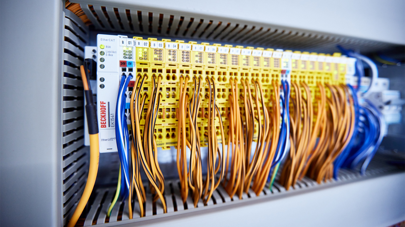
The sequences are programmed in TwinCAT 3. The test specimens are connected via a separate controller (CX5130 Embedded PC) and controlled via an EL669x EtherCAT bridge terminal. According to Dr. Wilfried Holzke, “This provides an advantage; the program can be individually adapted to the test specimen without having to modify the main controller (C5102 19-inch rack-mount IPC). As the test specimens are changing constantly, the communication terminals also have to change continuously,” he adds, pointing out another advantage of EtherCAT and PC-based control. The wide-ranging portfolio of EtherCAT components meant it made sense to implement a large part of the cabling in POV/fiber optic multi-mode. Ultimately, fiber optic cables are resistant to the electromagnetic interference that is inevitable at high currents and frequencies.
As many as ten controllers are used in the complete test facility, including the pre-test platform and test station. In addition to three C5102 19-inch rack-mount IPCs (main control system, pre-test platform, and test station), six CX5130 Embedded PCs are used for the test specimens, along with one CX7080 Embedded PC. A CP2916 multi-touch built-in Control Panel is integrated into a generic demonstrator for controlling the frequency converters. Almost the entire spectrum of EtherCAT Terminals is installed, starting with digital I/Os, A/D and D/A converters, and encoder I/Os. Safe operation of the facility is monitored by TwinSAFE Terminals, such as EL1904 and EL2904, with a total of over 620 safety channels. The TwinSAFE project is controlled system-wide via ten EL6910 TwinSAFE Logic Terminals.
EtherCAT Hot Connect allows preconfigured sections to be removed from or added to the data traffic before system startup or during operation. This results in further advantages for partial shutdowns in hazardous situations in the vicinity of the test specimen or for modifications. The EtherCAT distributed clock function also offers interesting potential for development here. “This would allow complete and continuous synchronization from the main control to pulse pattern generation,” Dr. Wilfried Holzke reveals, outlining how the project is set to develop.