
XFC | eXtreme Fast Control Technology
The fast control solution XFC is based on an optimized control and communication architecture. With XFC it is possible to realize I/O response times < 100 μs.
Headquarters New Zealand
Beckhoff Automation Limited

The fast control solution XFC is based on an optimized control and communication architecture. With XFC it is possible to realize I/O response times < 100 μs.
With XFC technology (eXtreme Fast Control Technology) in 2008 Beckhoff presented an ultra fast control solution: XFC is based on optimized control and communication architectures comprising an advanced Industrial PC, ultra-fast I/O terminals with extended real-time characteristics, the EtherCAT high-speed Ethernet system, and the TwinCAT automation software. With XFC it is possible to achieve I/O response times < 100 μs.
XFC represents a control technology that enables very fast and highly deterministic responses. It includes all hardware and software components involved in control applications: optimized input and output components that can detect signals with high accuracy or initiate tasks; EtherCAT as very fast communication network; high-performance Industrial PCs; and TwinCAT, the automation software that links all system components.
Not long ago, control cycle times around 10 to 20 ms were normal. The communications interface was free-running, with corresponding inaccuracy of the determinism associated with responses to process signals. The increased availability of high-performance Industrial PC controllers enabled a reduction in cycle times down to 1–2 ms, i.e. by about a factor of 10. Many special control loops could thus be moved to the central machine controller, resulting in cost savings and greater flexibility in the application of intelligent algorithms.
XFC offers a further reduction of response times by a factor of 10, and enables cycle times of 100 μs, without having to give up central intelligence and associated high-performance algorithms. XFC also includes additional technologies that not only improve cycle times, but also temporal accuracy and resolution.
Users benefit from entirely new options for enhancing the quality of their machines and reducing response times. Measuring tasks such as preventive maintenance measures, monitoring of idle times or documentation of parts quality can simply be integrated in the machine control without additional, costly special devices.
In a practical automation solution, not everything has to be extremely fast and accurate – many tasks can still be handled with “normal” solutions. XFC technology is therefore fully compatible with existing solutions and can be used simultaneously with the same hardware and software.
In a normal, discrete control loop, actual value acquisition occurs at a certain time (input component), the result is transferred to the control system (communication component), the response is calculated (control component), the result is communicated to the set value output module (output component) and issued to the process (controlled system).
The crucial factors for the control process are: minimum response time, deterministic actual value acquisition (i.e. exact temporal calculation must be possible), and corresponding deterministic set value output. At what point in time the communication and calculation occurs in the meantime is irrelevant, as long as the results are available in the output unit in time for the next output, i.e. temporal precision is required in the I/O components, but not in the communication or the calculation unit.
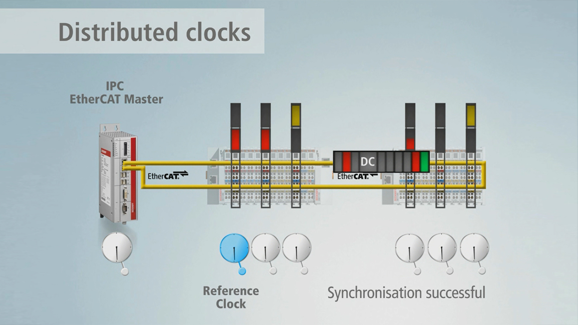
The distributed EtherCAT clocks therefore represent a basic XFC technology and are a general component of EtherCAT communication. All EtherCAT devices have their own local clocks, which are automatically and continuously synchronized with all other clocks via the EtherCAT communication. Different communication runtimes are compensated, so that the maximum deviation between all clocks is generally less than 100 ns. The current time of the distributed clocks is therefore also referred to as system time, because it is always available across the whole system.
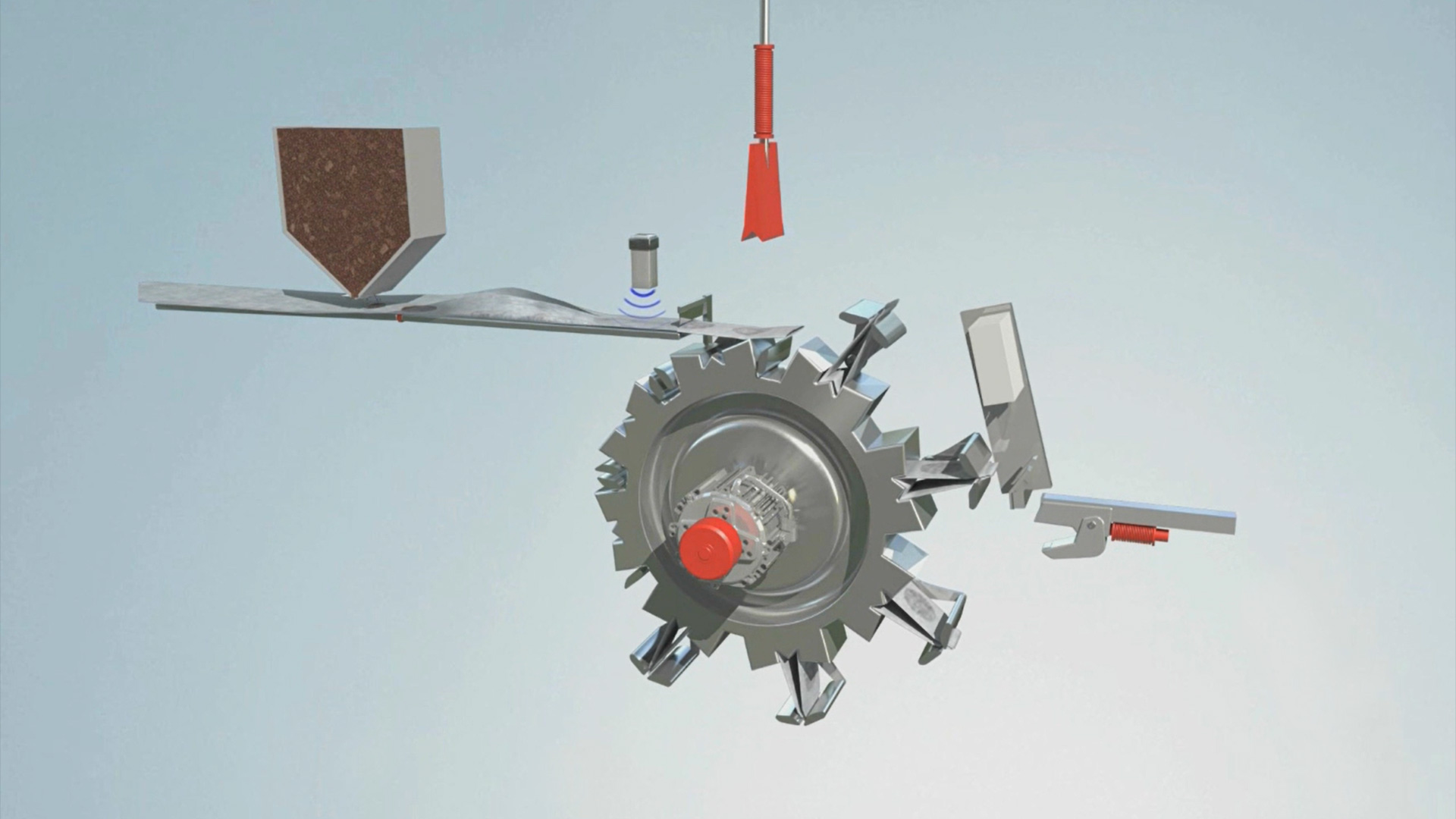
Process data is usually transferred in its respective data format (e.g. one bit for a digital value or one word for an analog value). The temporal relevance of the process record is therefore inherent in the communication cycle during which the record is transferred. However, this also means that the temporal resolution and accuracy is limited to the communication cycle.
Timestamped data types contain a timestamp in addition to their user data. This timestamp – naturally expressed in the ubiquitous system time – enables provision of temporal information with significantly higher precision for the process record. Timestamps can be used for inputs (e.g. to identify the time that an event occurred) and outputs (e.g. timing of a response). This way, it is possible to determine, for example, the precise point in time when an output is to be switched. The switching task is executed independently of the bus cycle.
While timestamp terminals can execute one switching task or switching event per bus cycle, multi-timestamp terminals can execute up to 32 switching tasks or switching events per cycle.
Process data is usually transferred exactly once per communication cycle. Conversely, the temporal resolution of a process record directly depends on the communication cycle time. Higher temporal resolution is only possible through a reduction in cycle time – with associated practical limits.
Oversampling data types enable multiple sampling of a process record within a communication cycle and subsequent (inputs) or prior (outputs) transfer of all data contained in an array. The oversampling factor describes the number of samples within a communication cycle and is therefore a multiple of one. Sampling rates of 200 kHz can easily be achieved, even with moderate communication cycle times.
Triggering of the sampling within the I/O components is controlled by the local clock (or the global system time), which enables associated temporal relationships between distributed signals across the whole network.
Very fast physical responses require suitably short control cycle times in the associated control system. A response can only take place once the control system has detected and processed an event.
The traditional approach for achieving cycle times in the 100 μs range relies on special separate controllers with their own, directly controlled I/Os. This approach has clear disadvantages, because the separate controller has only very limited information about the overall system and therefore cannot make higher-level decisions. Reparameterization options (e.g. for new workpieces) are also limited. Another significant disadvantage is the fixed I/O configuration, which generally cannot be expanded.
Implementation of the XFC technologies described above requires full support for all hardware and software components involved in the control system, including fast, deterministic communication and I/O and control hardware. A significant part of XFC are the software components responsible for fast processing of the control algorithms and optimized configuration of the overall system.
Beckhoff offers a special XFC product range based primarily on five categories: EtherCAT as fieldbus, EtherCAT Terminals as I/O system, IPCs as hardware platform, servo drives as motion components and TwinCAT as higher-level software. All components are based on open standards, which means that any engineer or programmer can develop very fast control solutions with high performance based on standard components (i.e. without special hardware).
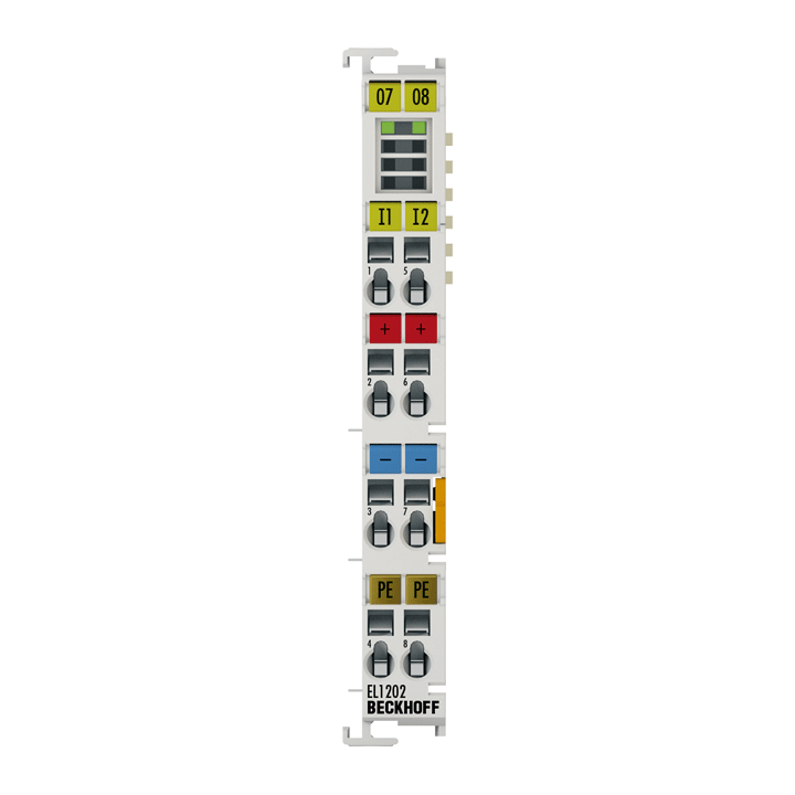
The EL1202 digital input terminal acquires the binary 24 V control signals from the process level and transmits them, in an electrically isolated form, to the higher-level automation unit. The EtherCAT Terminal contains two channels whose signal state is indicated by LEDs.
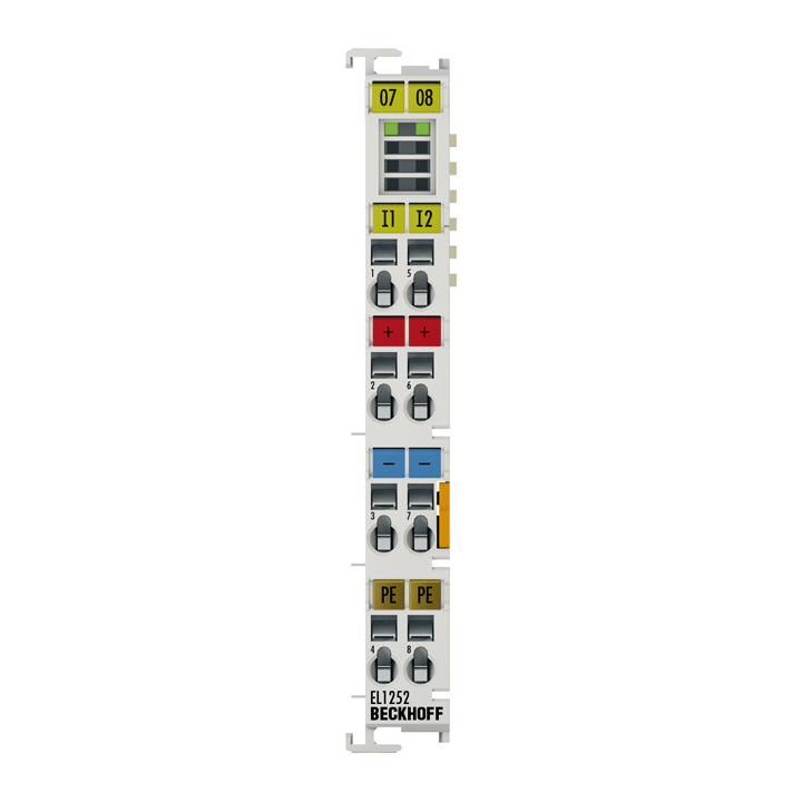
The EL1252 digital input terminal acquires the fast binary 24 V control signals from the process level and transmits them, in an electrically isolated form, to the controller. The EtherCAT Terminal contains two channels whose signal state is indicated by LEDs. The signals are furnished with a time stamp that identifies the time of the last edge change with a resolution of 1 ns. With this XFC technology, signal characteristics can be traced exactly in time and correlated with the distributed clocks system-wide. With this technology, machine-wide parallel hardware wiring of digital inputs or encoder signals for synchronization purposes is often no longer required. In conjunction with the EL2252 EtherCAT Terminal (digital output terminal with time stamp), the EL1252 enables responses with equidistant time intervals, largely independent of the bus cycle time.
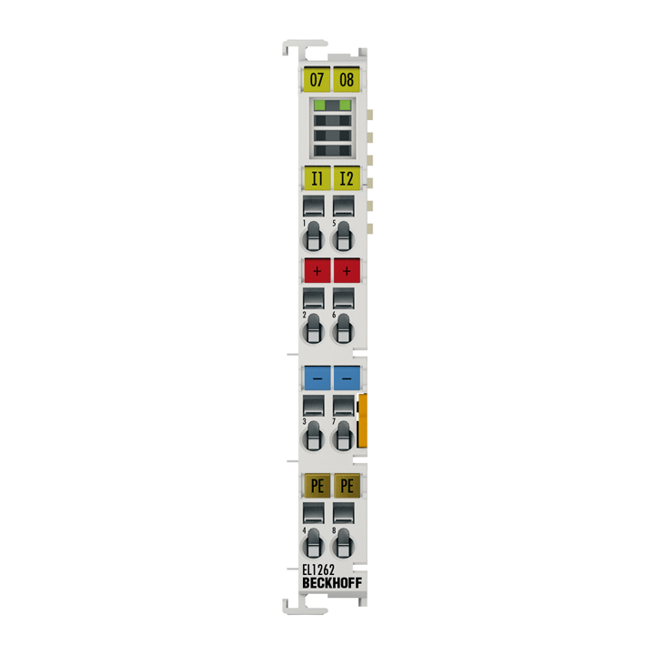
The EL1262 digital input terminal acquires the fast binary 24 V control signals from the process level and transmits them, in an electrically isolated form, to the controller. The EtherCAT Terminal has two channels that indicate their signal state via light emitting diodes. The signals are sampled with a configurable, integer multiple (oversampling factor: n) of the bus cycle frequency (n microcycles per bus cycle). For each bus cycle, the EtherCAT Terminal generates a process data block that is transferred collectively during the next bus cycle. The timebase of the terminal can be synchronized precisely with other EtherCAT devices via distributed clocks. This XFC procedure enables the temporal resolution of the digital input signals to be increased to n times the bus cycle time.
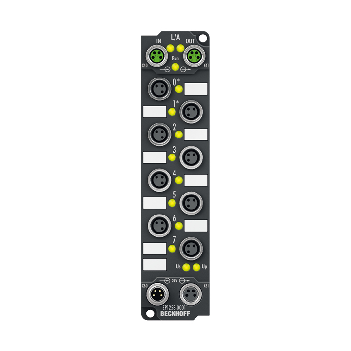
The EP1258-0001 EtherCAT Box with digital inputs acquires the fast binary control signals from the process level and transmits them, in an electrically isolated form, to the controller. The signals are furnished with a timestamp that identifies the time of the last edge change with a resolution of 1 ns. This technology enables signals to be traced exactly over time and synchronized with the distributed clocks across the system. With this technology, machine-wide parallel hardware wiring of digital inputs or encoder signals for synchronization purposes is often no longer required. In this way, the EP1258 enables responses with equidistant time intervals, largely independent of the bus cycle time.
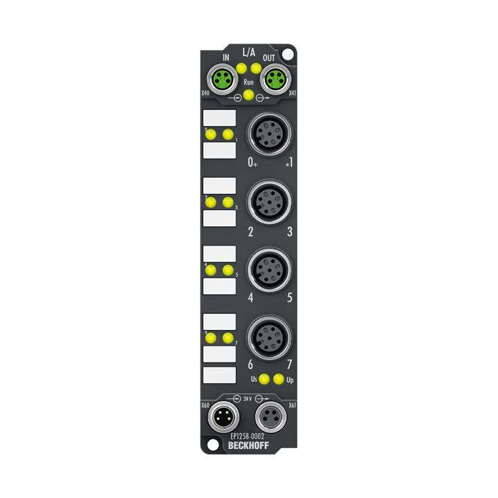
The EP1258-0002 EtherCAT Box with digital inputs acquires the fast binary control signals from the process level and transmits them, in an electrically isolated form, to the controller. The signals are furnished with a timestamp that identifies the time of the last edge change with a resolution of 1 ns. This technology enables signals to be traced exactly over time and synchronized with the distributed clocks across the system. With this technology, machine-wide parallel hardware wiring of digital inputs or encoder signals for synchronization purposes is often no longer required. In this way, the EP1258 enables responses with equidistant time intervals, largely independent of the bus cycle time.
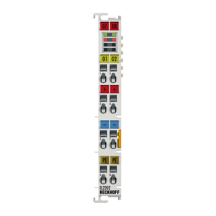
The EL2202/EL2202-0100 digital output terminal connects the binary control signals from the automation device on to the actuators at the process level with electrical isolation. This terminal benefits from very small output delay and is therefore suitable for signals requiring particularly fast output. The EtherCAT Terminal has a push-pull output that can be actively switched to 24 V, 0 V or high-impedance. The EL2202-0100 contains two channels. LEDs indicate the signal state of each channel.
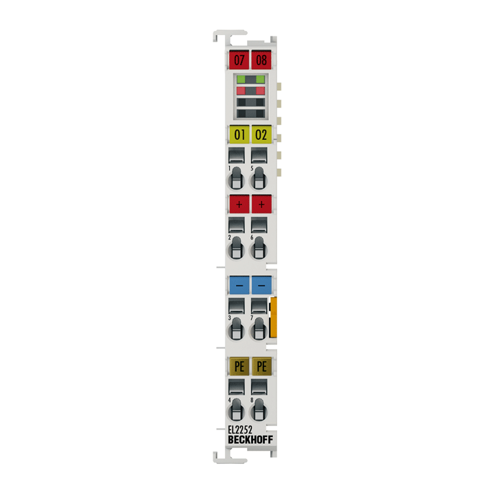
The EL2252 digital output terminal connects the binary control output signals at the process level with electrical isolation. The outputs of the EtherCAT Terminal are switched with high precision to match the transferred timestamp, which has a resolution of 10 ns. This technology enables output switching times to be specified precisely across the system. The distributed clocks are used for reference. In conjunction with the EL1252 (digital input terminal with time stamp), the EL2252 enables responses with equidistant time intervals, largely independent of the bus cycle time. Each output can be switched to high resistance individually.
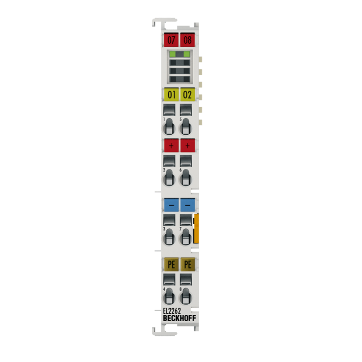
The EL2262 digital output terminal connects the binary control output signals at the process level with electrical isolation. The outputs are controlled with an adjustable integral multiple (oversampling factor: n) of the bus cycle frequency (n microcycles per bus cycle). For each bus cycle, the EtherCAT Terminal receives a process data block that is output consecutively. The timebase of the terminal can be synchronized precisely with other EtherCAT devices via distributed clocks. An output pattern with a significantly higher pulse sequence than the bus cycle time is thus output precisely with the system-wide timebase. This procedure enables the temporal resolution of the digital output signals to be increased to n times the bus cycle time. The maximum output rate is 1 Msamples/s.
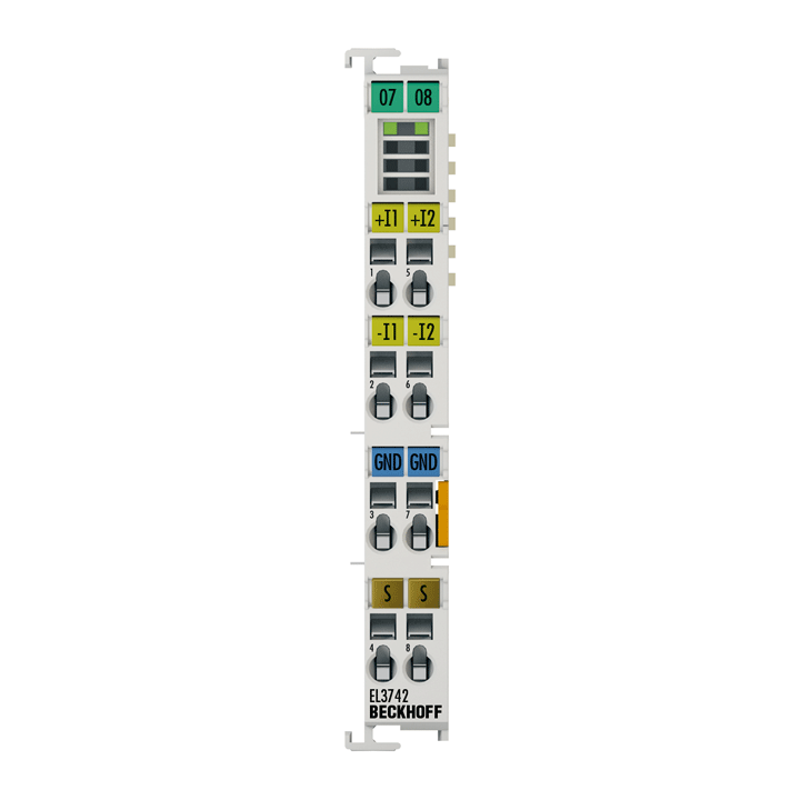
The EL3742 analog input terminal handles signals in the range between 0 and 20 mA. The voltage is digitized to a resolution of 16 bits, and is transmitted, electrically isolated, to the controller. The input channels of the EtherCAT Terminal have differential inputs and possess a common, internal ground potential. The signals are oversampled with an adjustable, integer multiple (oversampling factor: n) of the bus cycle frequency (n microcycles per bus cycle). For each bus cycle, the EtherCAT Terminal generates a process data block that is collected and transferred during the next bus cycle. The time base of the terminal can be synchronized precisely with other EtherCAT devices via distributed clocks. This procedure enables the temporal resolution of the analog input signals to be increased to n times the bus cycle time. In conjunction with the EL47xx (analog output terminal with oversampling), responses with equidistant time intervals, e.g. in the event of a threshold value being exceeded, become possible. The distributed clocks function enables several EL3742 devices to be synchronized in almost any configuration. The maximum sampling rate per channel is 100 ksamples/s (100,000 samples/s).
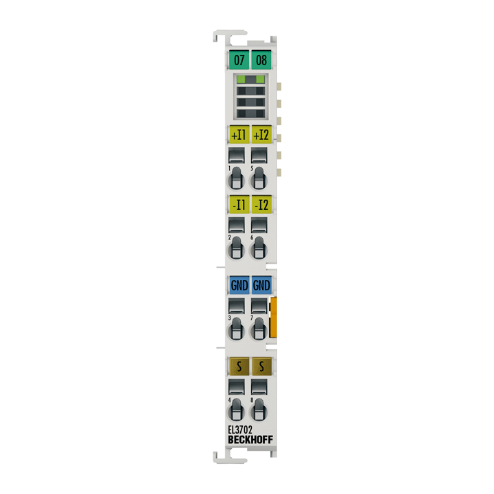
The EL3702 analog input terminal handles signals in the range between -10 and +10 V. The voltage is digitized to a resolution of 16 bits, and is transmitted, electrically isolated, to the controller. The signals are oversampled with an adjustable, integer multiple (oversampling factor: n) of the bus cycle frequency (n microcycles per bus cycle). For each bus cycle, the EtherCAT Terminal generates a process data block that is transferred collectively during the next bus cycle. The time base of the terminal can be synchronized precisely with other EtherCAT devices via distributed clocks. This procedure enables the temporal resolution of the analog input signals to be increased to n times the bus cycle time. In conjunction with the EL47xx (analog output terminal with oversampling), responses with equidistant time intervals, e.g. in the event of a threshold value being exceeded, become possible.
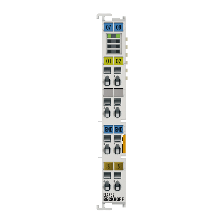
The EL4732 analog output terminal generates signals in the range between -10 V and +10 V. The voltage is supplied to the process level with a resolution of 16 bits and is electrically isolated. The output channels have a common ground potential. The outputs are oversampled with an adjustable, integer multiple (oversampling factor: n) of the bus cycle frequency (n microcycles per bus cycle). For each bus cycle, the EtherCAT Terminal receives a process data block that is output consecutively. The time base of the terminal can be synchronized precisely with other EtherCAT devices via distributed clocks. This procedure enables the temporal resolution of the analog output signals to be increased to n times the bus cycle time. In conjunction with the EL37xx (analog input terminal with oversampling), responses with equidistant time intervals, e.g. in the event of a threshold value being exceeded, become possible. The EL4732 device can output a maximum of 100,000 values (100 ksamples/s) per channel and second.
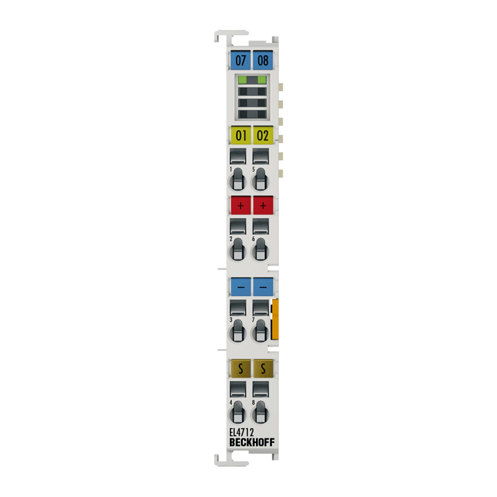
The EL4712 analog output terminal generates output signals in the range between 0 and 20 mA. The voltage is supplied to the process level with a resolution of 16 bits and is electrically isolated. The output channels have a common ground potential. The outputs are sampled with an adjustable, integer multiple (oversampling factor: n) of the bus cycle frequency (n microcycles per bus cycle). For each bus cycle, the EtherCAT Terminal receives a process data block that is output consecutively. The time base of the terminal can be synchronized precisely with other EtherCAT devices via distributed clocks. This procedure enables the temporal resolution of the analog output signals to be increased to n times the bus cycle time. In conjunction with the EL37xx (analog input terminal with oversampling), responses with equidistant time intervals, e.g. in the event of a threshold value being exceeded, become possible. The EL4712 device can output a maximum of 100,000 values (100 ksamples/s) per channel and second.
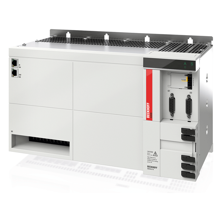
The AX8525 and AX8540 combined power supply and axis modules unite the function of an AX86xx power supply module with an AX81xx axis module in a single device. As a result, the AX-Bridge is not loaded by the axis current of the first axis and up to 50 A DC are available for additional axis modules. The power supply provides 80 A DC to the DC link and contains an internal brake resistor as well as a chopper for the connection of an external brake resistor. The integrated axis module with TwinSAFE safety functions is available with a rated current of 25 A or 40 A and can optionally be ordered with multi-feedback interface.

The AX8525 and AX8540 combined power supply and axis modules unite the function of an AX86xx power supply module with an AX81xx axis module in a single device. As a result, the AX-Bridge is not loaded by the axis current of the first axis and up to 50 A DC are available for additional axis modules. The power supply provides 80 A DC to the DC link and contains an internal brake resistor as well as a chopper for the connection of an external brake resistor. The integrated axis module with TwinSAFE safety functions is available with a rated current of 25 A or 40 A and can optionally be ordered with multi-feedback interface.
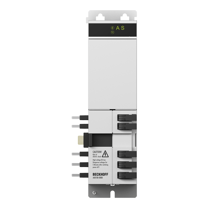
An axis module contains the DC link and the inverter for supplying the motor. Depending on the required number of axes, the axis modules are attached to the power supply module to form the multi-axis servo system. Axis modules with different ratings can be combined in order to enable an optimized design of the individual axes.
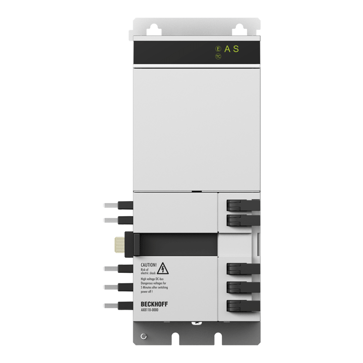
An axis module contains the DC link and the inverter for supplying the motor. Depending on the required number of axes, the axis modules are attached to the power supply module to form the multi-axis servo system. Axis modules with different ratings can be combined in order to enable an optimized design of the individual axes.
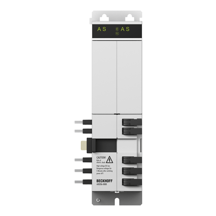
An axis module contains the DC link and the inverter for supplying the motor. Depending on the required number of axes, the axis modules are attached to the power supply module to form the multi-axis servo system. Axis modules with different ratings can be combined in order to enable an optimized design of the individual axes.