
EL3142-0010 | EtherCAT Terminal, 2-channel analog input, current, ±10 mA, 16 bit, single-ended


+24 V DC
0 V

EL3142-0010 | EtherCAT Terminal, 2-channel analog input, current, ±10 mA, 16 bit, single-ended
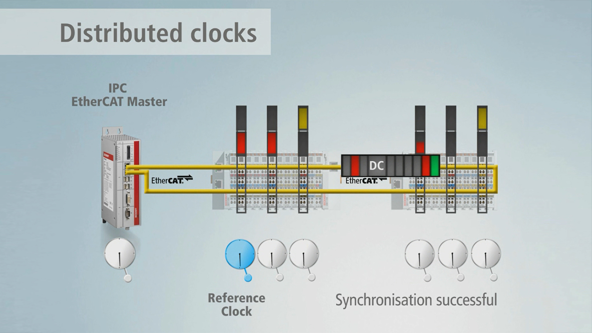
Distributed Clocks: the integrated time management system in EtherCAT
Measurement technology easily configured: Analog EtherCAT input terminals.
Measurement technology simply integrated: With the analog EtherCAT Terminals.

Decentralised, end-to-end system synchronisation: With Distributed Clocks and EtherCAT.

The job of the EL3142-0010 analog input terminal is to supply power to measuring transducers located in the field, and to transmit analog measurement signals with electrical isolation to the automation device. The voltage for the sensors is supplied to the terminals via the power contacts. The power contacts can optionally be supplied with operating voltage in the standard way or via a supply terminal (EL9xxx) with electrical isolation. The input electronics is independent of the supply voltage of the power contacts. The 0 V power contact is the reference potential for the inputs. The EtherCAT Terminal indicates its signal state by means of light emitting diodes.
Product status:
regular delivery
Product information
| Technical data | EL3142-0010 |
|---|---|
| Number of inputs | 2 (single-ended) |
| Wiring | 1-wire, 2-wire, 3-wire, 4-wire |
| Ground reference (input) | single-ended |
| Power supply | via the E-bus |
| Signal current | -10…+10 mA |
| Oversampling factor | – |
| Input signal bandwidth | see input filter |
| Distributed clocks | yes |
| Distributed clock precision | << 1 µs |
| Internal resistance | typ. 85 Ω + diode voltage |
| Input filter limit frequency | 5 kHz |
| Dielectric strength | max. 30 V |
| Conversion time | ~ 60 µs (fast mode ~ 40 µs) |
| Resolution | 16 bit (incl. sign) |
| Measurement error/uncertainty | < ±0.3% (relative to full scale value) |
| Electrical isolation | 500 V (E-bus/signal voltage) |
| Current consumption E-bus | typ. 170 mA |
| Current consumption power contacts | – |
| Bit width in the process image | inputs: 8 byte |
| Special features | standard and compact process image, switchable measuring data representation, activatable FIR/IIR filters, limit value monitoring |
| Weight | approx. 60 g |
| Operating temperature | -25…+60°C |
| Storage temperature | -40…+85°C |
| Relative humidity | 95%, no condensation |
| Vibration/shock resistance | conforms to EN 60068-2-6/EN 60068-2-27 |
| EMC immunity/emission | conforms to EN 61000-6-2/EN 61000-6-4 |
| Protect. rating/installation pos. | IP20/variable |
| Approvals/markings | CE, UL |
| Housing data | EL-12-8pin |
|---|---|
| Design form | compact terminal housing with signal LEDs |
| Material | polycarbonate |
| Installation | on 35 mm DIN rail, conforming to EN 60715 with lock |
| Side by side mounting by means of | double slot and key connection |
| Marking | labeling of the BZxxxx series |
| Wiring | solid conductor (s), flexible conductor (st) and ferrule (f): spring actuation by screwdriver |
| Connection cross-section | s*: 0.08…2.5 mm², st*: 0.08…2.5 mm², f*: 0.14…1.5 mm² |
| Connection cross-section AWG | s*: AWG28…14, st*: AWG28…14, f*: AWG26…16 |
| Stripping length | 8…9 mm |
| Current load power contacts | Imax: 10 A |
| Dimensions (W x H x D) | 12 mm x 100 mm x 68 mm |
*s: solid wire; st: stranded wire; f: with ferrule
Loading content ...
Loading content ...
Loading content ...
Loading content ...
© Beckhoff Automation 2025 - Terms of Use