
EJ1101-0022 | EtherCAT plug-in module, EtherCAT Coupler, external bus interface, separate power supply

EJ1101-0022 | EtherCAT plug-in module, EtherCAT Coupler, external bus interface, separate power supply

EJ1101-0022 | Combination with external power supply plug-in module, RJ45 sockets and ID switches

EJ1101-0022 | EtherCAT plug-in module, EtherCAT Coupler, external bus interface, separate power supply

EJ1101-0022 | EtherCAT plug-in module, EtherCAT Coupler, external bus interface, separate power supply

EJ1101-0022 | Combination with external power supply plug-in module, RJ45 sockets and ID switches
EtherCAT plug-in modules of the EJ series
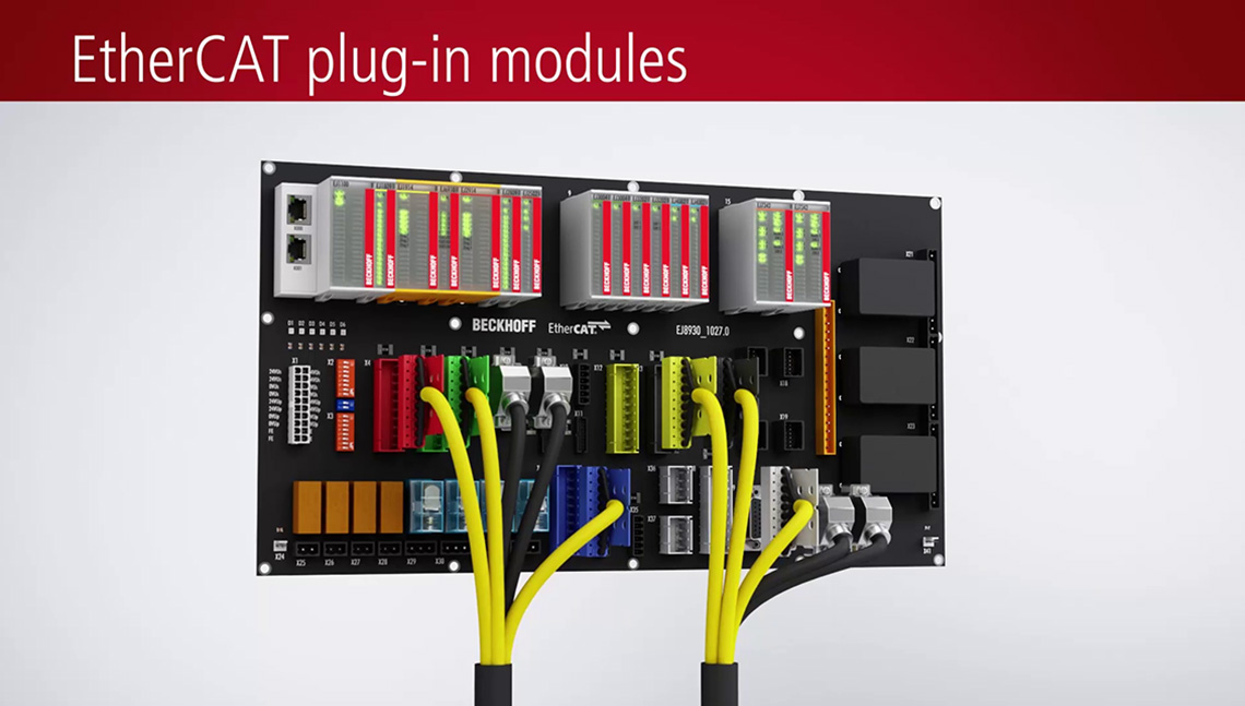
EtherCAT plug-in modules: Bus Terminals for circuit boards

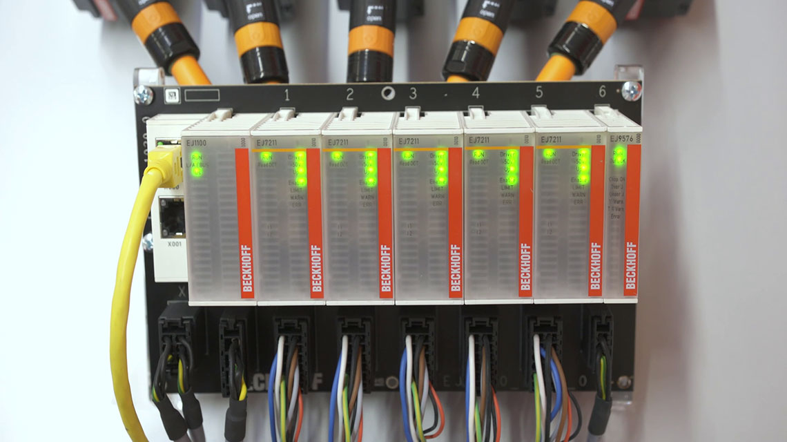
The EJ1101-0022 EtherCAT Coupler is the link between the EtherCAT protocol at fieldbus level and the EtherCAT plug-in modules. The external RJ45 sockets, ID switches and power supply plug-in modules allow a wide range of installation options. For power supply of the attached EtherCAT plug-in modules, the coupler must be combined with the external power supply plug-in modules EJ9400 (2.5 A) or EJ9404 (12 A). Power supply plug-in modules, RJ45 sockets as well as ID switches are not included in the scope of delivery.
The coupler converts the passing telegrams from Ethernet 100BASE-TX to E-bus signal representation. A module station consists of a coupler and any number of EtherCAT plug-in modules, which are automatically detected and individually displayed in the process image.
Special features:
- Connection technology: 2 x RJ45 socket, external for positioning directly on the signal distribution board
- Connection lengths up to 100 km
- two external ID switches for implementing variable topologies
- Combination with external plug-in power supply module
- Offers versatile installation options: Control cabinet feed-throughs, housing installation
The RJ45 sockets are external and allow positioning directly on the signal distribution board. The coupler is connected to the network via the upper EtherCAT interface. The lower external RJ45 socket can be used to connect further EtherCAT devices in the same line. A unique ID can be assigned to a group of EtherCAT components via the external hexadecimal ID switches. This group can then be positioned anywhere in the EtherCAT network. Variable topologies are therefore easily implementable.
Product status:
regular delivery
Product information
| Technical data | EJ1101-0022 |
|---|---|
| Task within EtherCAT system | coupling of EtherCAT plug-in modules (EJxxxx) to 100BASE-TX EtherCAT networks |
| Distance between stations | max. 100 m (100BASE-TX) |
| Transmission medium | Industrial Ethernet/EtherCAT cable (min. Cat.5), shielded |
| ID switch | external (optional, not included) |
| Diagnostics | over-/undervoltage via EtherCAT CoE |
| Protocol | EtherCAT |
| Propagation delay | typ. 1 µs |
| Transmission rate | 100 Mbit/s |
| Bus interface | plug connector on the signal distribution board, e.g. 2 x RJ45 |
| Power supply | 24 V DC (-15%/+20%) |
| Current consumption E-bus | typ. 310 mA |
| Current supply E-bus | external via EJ94xx |
| Electrical isolation | 500 V (power contact/supply voltage/Ethernet) |
| Weight | approx. 30 g |
| Operating temperature | -25…+60°C |
| Storage temperature | -40…+85°C |
| Relative humidity | 95%, no condensation |
| Vibration/shock resistance | conforms to EN 60068-2-6/EN 60068-2-27 |
| EMC immunity/emission | conforms to EN 61000-6-2/EN 61000-6-4 |
| Protect. rating/installation pos. | IP20/see documentation |
| Approvals/markings | CE, UL |
| Housing data | EJ_12_16pin |
|---|---|
| Weight | approx. 60 g |
| Protection rating | IP20 |
| Material | polycarbonate |
| Dimensions | Width (single) | 12 mm |
| Dimensions | Height | 66 mm |
| Dimensions | Depth | 55 mm |
| Installation | 2 x 20-pin socket strip on signal distribution board |
| Connection mechanism | application-specific plug on the signal distribution board |
| Mechanical coding | no |
Loading content ...
Loading content ...
Loading content ...
Loading content ...
Loading content ...
Loading content ...
© Beckhoff Automation 2026 - Terms of Use